Articles with tag: "ice protection"

(Note: figures do not appear in the summaries below)
  1. NACA-RM-E53A22

    "radome icing has serious effects on the radar operation"

    "An Analytical Study of Heat Requirements for Icing Protection of Radomes"

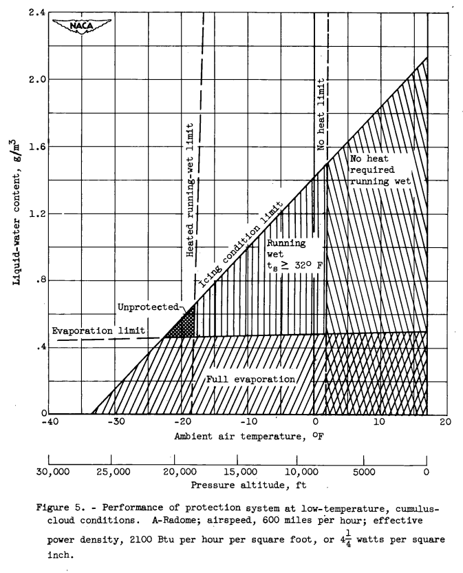
    Figure 5. Performance of protection system at low-temperature, cumulus-
cloud conditions. A-Radome; airspeed, 600 miles pr hour; effective
power density, 2100 Btu per hour per square foot, or
inch.

    Abstract

    The heat requirements for the icing protection of two radome configurations have been studied. over a range of design icing conditions. Both the protection limits of a typical thermal protection system and the relative effects of the various icing variables have been determined. For full evaporation of all impinging water, an effective heat density of 14 watts per square inch was required. When a combination of the full evaporation and running-wet surface systems was employed, a heat requirement of 5 watts per square inch provided protection at severe icing and operating conditions.

    Discussion

    INTRODUCTION

    Radar is becoming of increasing importance in the design and operation of aircraft. Successful operation of these aircraft demands that the performance of the radar system including the radome be unimpaired by environmental factors including …

    read more
  2. NACA-RM-E57G09

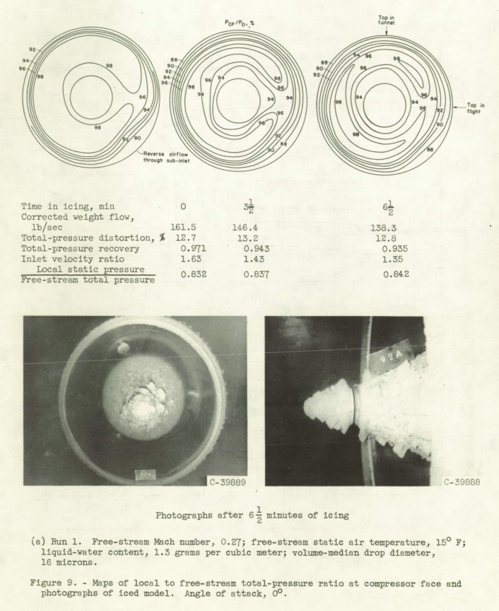
    "the contour plots indicate that cowl-lip disturbances are the more controlling factor"

    "Total Pressure Distortion and Recovery of Supersonic Nose Inlet with Conical Centerbody in Subsonic Icing Conditions" 1

    Figure 9. Maps of local to free-stream total-pressure ratio at compressor face and
photographs of iced model. Angle of attack, 0°.

    Abstract

    Ice was formed on a full-scale unheated supersonic nose inlet in the NACA Lewis icing tunnel to determine its effect on compressor-face total-pressure distortion and recovery. Inlet angle of attack was varied from 0° to 12°, free-stream Mach number from 0.17 to 0.28, and compressor-face Mach number from 0.10 to 0.47. Icing-cloud liquid-water content was varied from 0.65 to 1.8 grams per cubic meter at free-stream static air temperatures of 15° and 0° F.

    The addition of ice to the inlet components increased total-pressure- distortion levels and decreased recovery values compared with clear-air results, the losses increasing with time in ice. The combination of glaze ice, high corrected weight flow, and high angle of …

    read more
  3. NACA-TN-4093

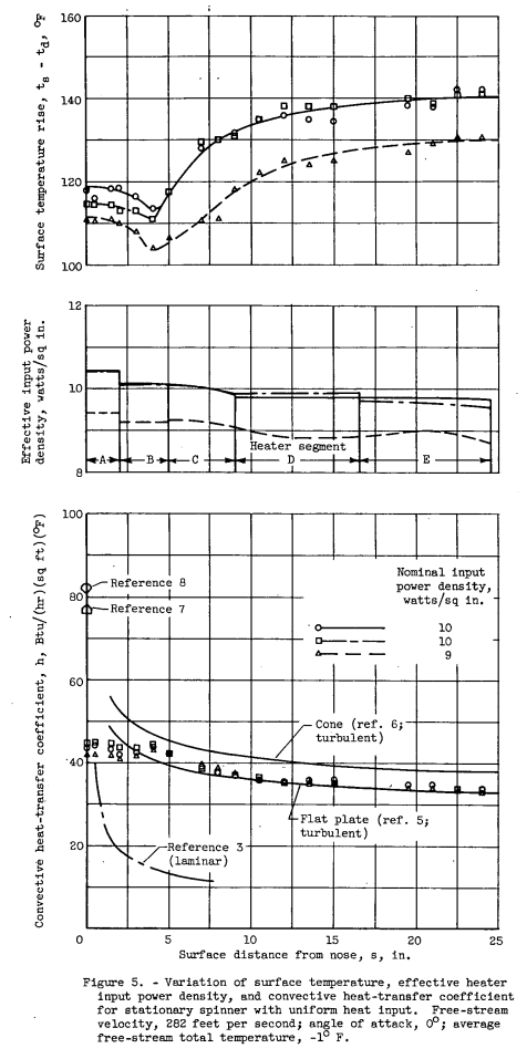
    "Rotational speeds up to 1200 rpm had no apparent effect on the heat-transfer characteristics of the spinner"

    "Investigation of Heat Transfer from a Stationary and Rotating Conical Forebody"

    Figure 5. Variation of surface temperature, effective heater
input power density, and convective heat-transfer coefficient
for stationary spinner with uniform heat input. Free-stream
velocity, 282 feet per second; angle of attack, 0°; average
free-stream total temperature, -1° F.

    Abstract

    The convective heat transfer from the surface of a conical forebody having a hemispherical nose, an included angle of approximately 30°, and a maximum diameter of 18.9 inches was investigated in a wind tunnel for both stationary and rotating operation. The range of test conditions included free-stream velocities up to 400 feet per second, rotational speeds up to 1200 rpm, and. angles of attack of 0° and 6°. Both a uniform surface temperature and a uniform heater input power density were used.

    The Nusselt-Reynold's number relations provided good correlation of the heat-transfer data for the complete operating range at 0° angle of attack with and without spinner rotation, and for 6° angle of attack with rotation. Rotational speeds up to …

    read more
  4. NACA-TN-3837

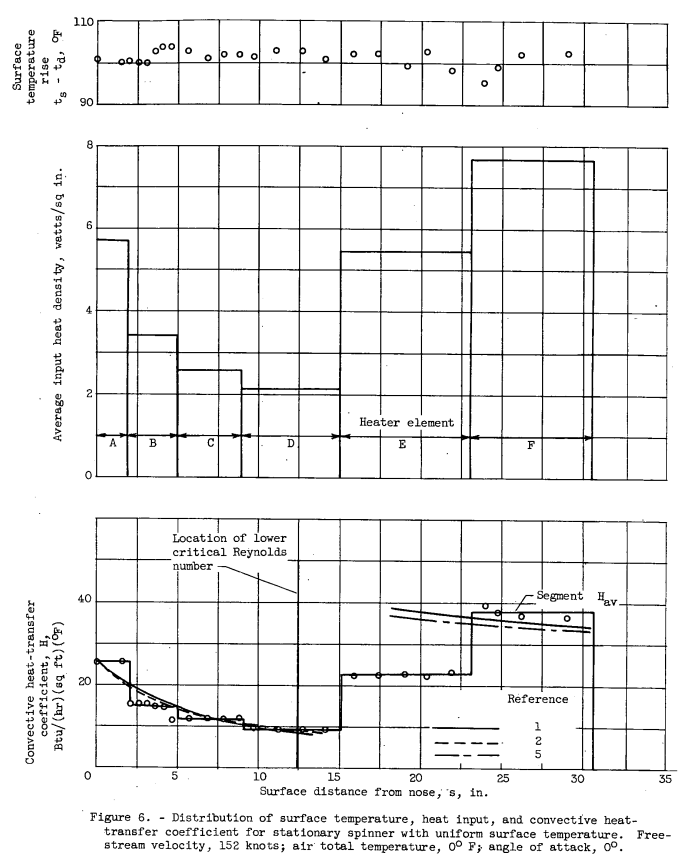
    "Many aircraft components are essentially simple bodies of revolution; examples of these are radomes, body noses, engine accessory housings, and the large spinners of turboprop engines"

    "Investigation of Heat Transfer from a Stationary and Rotating Ellipsoidal Forebody of Fineness Ratio 3" 1

    Figure 6. Distribution of surface temperature, heat input, and convective heat-transfer 
coefficient for stationary Spinner with uniform surface temperature. 
Free-stream velocity, 152 knots; air total temperature, 0° F; angle of attack, 0°.

    Abstract

    The convective heat transfer from the surface of an ellipsoidal fore-body of fineness ratio 3 and 20-inch maximum diameter was investigated in clear air for both stationary and rotating operation over a range of conditions including air speeds up to 240 knots, rotational speeds up to 1200 rpm, and angles of attack of 0°, 3°, and 6°. The results are presented in the form of heat-transfer coefficients and the correlation of Nusselt and Reynolds numbers. Both a uniform surface temperature and a uniform input heater density distribution were used.

    The experimental results agree well with theoretical predictions for uniform surface temperature distribution. Complete agreement was not obtained …

    read more
  5. NACA-RM-E51B12

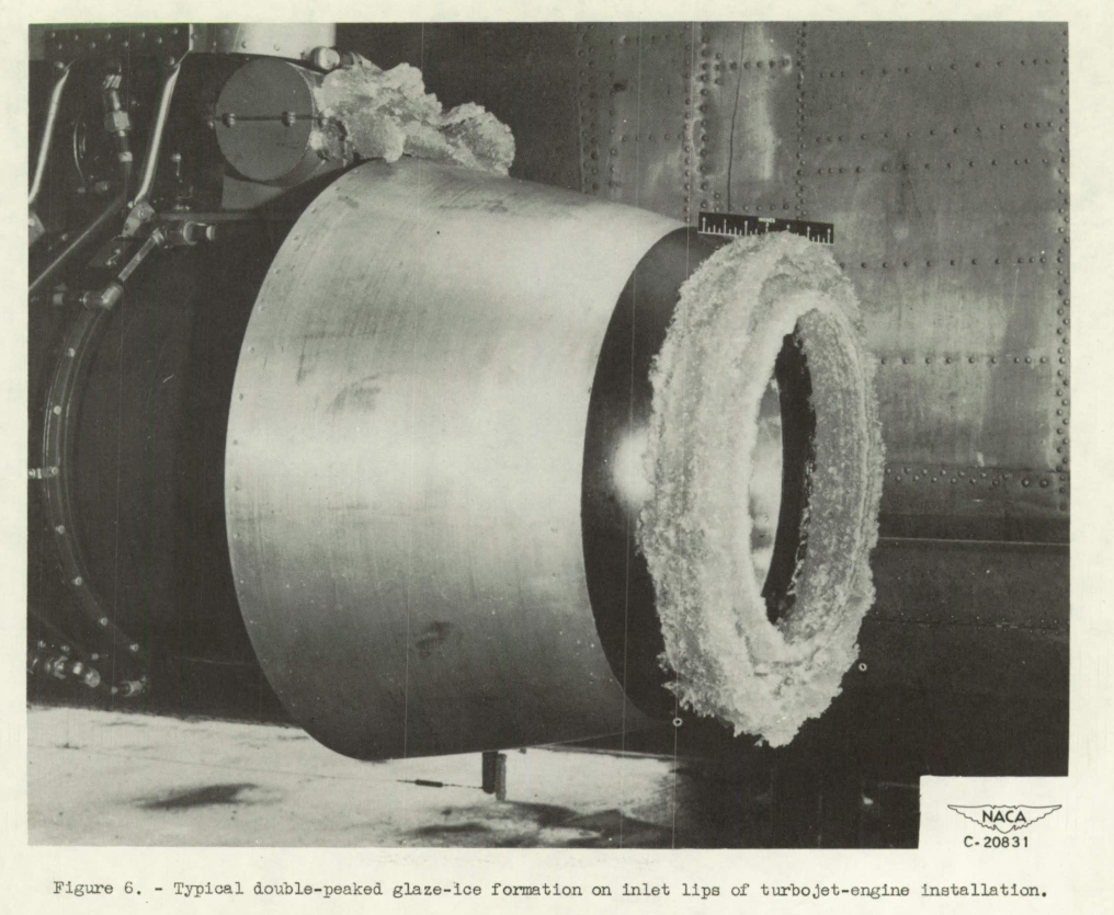
    "Serious icing of a turbojet-engine installation may render the engine inoperative in a matter of minutes."

    "NACA Investigations of Icing-Protection Systems for Turbojet-Engine Installations" 1

    Figure 6. Typical double-peaked glaze-ice formation on inlet lips of turbojet-engine installation.

    Abstract

    Investigations have been made in flight and in wind tunnels tc determine which components of turbojet installations are most critical in icing conditions, and to evaluate several methods of icing protection. From these studies, the requirements necessary for adequate icing protection and the consequent penalties on engine performance can be estimated.

    Because investigations have indicated that the compressor-inlet screen constitutes the greatest icing hazard and is difficult to protect, complete removal or retraction of the screen upon encountering an icing condition is recommended. In the absence of the screen, the inlet guide vanes of an axial-flow-type turbojet engine constitute the greatest danger to engine operation in an icing condition; a centrifugal- type engine, on the other hand, is relatively unsusceptible to icing once the …

    read more
  6. NACA-RM-E50H29

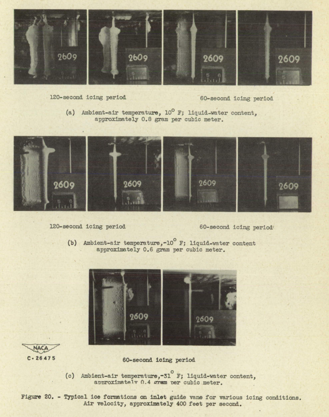
    "Experience has shown that ... the inlet guide vanes of an axial-flow turbojet engine constitute the most critical component to be protected from icing"

    "Investigation of Power Requirements for Ice Prevention and Cyclical De-Icing of Inlet Guide Vanes with Internal Electric Heaters" 1

    Figure 20. Typical ice formatione on inlet guide vane for various icing conditions, 
Air velocity, approximately 400 feet per second.

    Abstract

    An investigation was conducted to determine the electric power requirements necessary for ice protection of inlet guide vanes by continuous heating and by cyclical de-icing. Data are presented to show the effect of ambient-air temperature, liquid-water content, air velocity, heat-on period, and cycle times on the power requirements for these two methods of ice protection.
    The results showed that for a hypothetical engine using 28 inlet guide vanes under similar icing conditions, cyclical de-icing can provide a total power saving as high as 79 percent over that required for continuous heating. Heat-on periods in the order of 10 seconds with a cycle ratio of about 1:7 …

    read more
  7. NACA-RM-E50I08

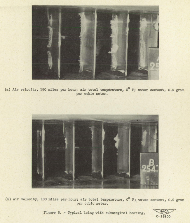
    "Ice formations ... may have the following effects, which when combined may become serious enough to necessitate a shutdown of the engine: reduced engine thrust, increased,fuel consumption, and increased tail-pipe temperature."

    "Icing Characteristics and Anti-Icing Heat Requirements for Hollow and Internally Modified Gas-Heated Inlet Guide Vanes" 1

    Figure 8. Typical icing with submarginal heating.

    Abstract

    A two-dimensional inlet-guide-vane cascade was investigated to determine the effects of ice formations on the pressure losses across the guide vanes and to evaluate the heated gas flow and temperature required to prevent icing at various conditions. A gas flow of approximately 0.4 percent of the inlet-air flow was necessary for anti-icing a hollow guide-vane stage at an inlet-gas temperature of 500° F under the following icing conditions: air velocity, 280 miles per hour; water content, 0.9 gram per cubic meter; and inlet-air static temperature, 0° F. Also presented are the anti-icing gas flows required with modifications of the hollow …

    read more
  8. NACA-TN-2126

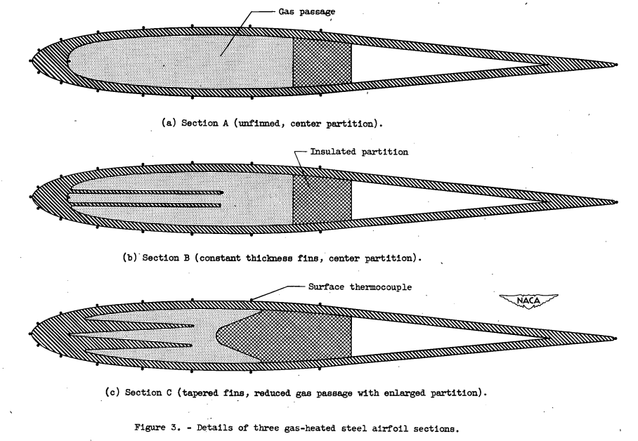
    "Use of the hot-gas method of anti-icing has been restricted ... because of difficulty in controlling the rate of heat dissipation"

    "Improvements in Heat Transfer for Anti-Icing of Gas-Heated Airfoils with Internal Fins and Partitions" 1

    Figure 3. Detail of three case-heated airfoil sections.

    Abstract

    The effect of modifying the gas passage of hollow metal airfoils by the additIon of internal fins and partitions was experimentally investigated and comparisons were made among a basic unfinned airfoil section and two airfoil designs having metal fins attached at the leading edge of the internal gas passage. An analysis considering the effects of heat conduction in the airfoil metal was made to determine the internal modification effectiveness that may be obtained in gas-heated components, such as turbojet-inlet guide vanes, support struts, hollow propeller blades, arid. thin wings.

    Over a wide range of heated-gas flow and tunnel-air velocity, the increase in surface-heating rates with internal fin was marked (up to 3.5 times …

    read more
  9. NACA-TN-1246

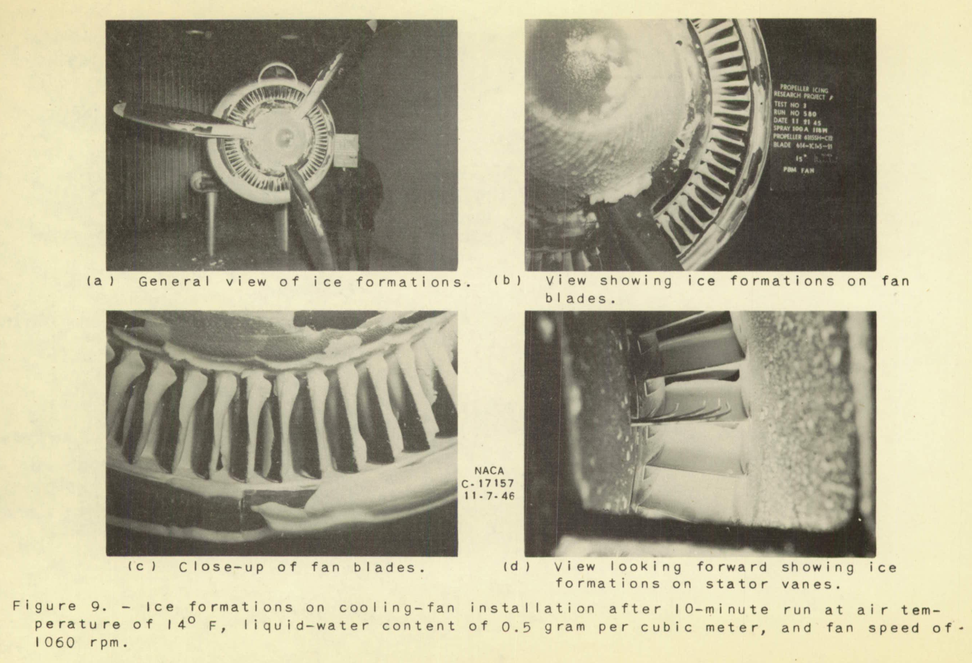
    "The icing of the unprotected installation presents a serious operational problem"

    "Wind-Tunnel Investigation of Icing of an Engine Cooling-Fan Installation" 1

    Figure 9. Ice formations on the cooling-fan installation after 
10-minute run at air temperature of 14 F, liquid-water content of 0.5 gram per cubic meter, 
and fan speed of 1060 rpm.

    Abstract

    An investigation was made of the icing characteristics and means of ice protection of a typIcal radial-engine cooling-fan installation, The investigation was made at various icing and performance conditions in the icing research tunnel of the NACA Cleveland laboratory.

    The icing of the unprotected cooling-fan installation was found to present a serious operational problem. Reduction in air flow below the minimum value required for engine cooling occurred within 2 minutes and complete stoppage of the cooling-air flow through the fan assembly occurred in as little as 5 minutes under normal icing conditions.

    Steam de-icing was found to be effective for the cowling lip and inlet duct. Alcohol de-icing of the fan blades and stator vanes was found to be unsatisfactory. Electrical heat de-icing of the fan blades was …

    read more
  10. Engine Inlet Icing

    "The desirability for all-weather operation of turbojet aircraft has necessitated extensive research on methods of icing protection for the various engine components"

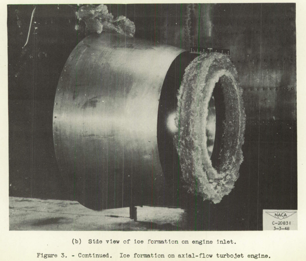
    Figure 3b. Ice formation on axial-flow turbojet engine. Side view of ice formation on engine inlet.
    From NACA-RM-E8C18.

    Discussion

    Publications taken largely from The Historical Selected Bibliography of NACA-NASA Icing Publications, "Turbine-Type Engine and Inlet Icing Studies" section are reviewed here.

    Reviews

    NACA-TN-1246 "Wind-Tunnel Investigation of Icing of an Engine Cooling-Fan Installation"

    • "The icing of the unprotected installation presents a serious operational problem"

    NACA-RM-E8C18 "Preliminary Results of Natural Icing of an Axial-Flow Turbojet Engine"

    • "Ice formations penetrated to the second-stage rotor blades"

    NACA-RM-E8FO1a "Natural Icing of an Axial-Flow Turbojet Engine in Flight for a Single Icing Condition"

    • "The engine was satisfactorily accelerated to take-off power after approximately 45 minutes in the icing condition"

    NACA-TN-2126 "Improvements in Heat Transfer for Anti-Icing of Gas-Heated Airfoils with Internal Fins and Partitions"

    • "Use of the hot-gas method of anti-icing has been restricted ... because of difficulty in controlling the …
    read more
  11. Conclusions of the Porter Perkins Series

    "our knowledge of aircraft icing and the penalties associated with it has not changed substantially in the last forty to fifty years" 1

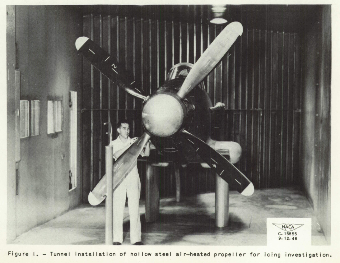
    Figure 1. Tunnel installation of hollow steel air-heated propeller for icing investigation. A tall, lean man with a distinctively tall nose inspects the propeller.

    From NACA-TN-1586. I believe that this is Porter Perkins, circa 1946.

    Summary

    The three areas of the many and varied contributions of Porter Perkins are reviewed.

    Discussion

    I will focus on three areas of Porter Perkins' publications:

    • Foresight about supercooled large drop (SLD) icing
    • A shift in instrument calibration
    • Contributions to the Appendix C icing regulation

    Foresight about supercooled large drop (SLD) icing

    I am not sure that I agree with the quote at the top (from 1993) now. A lot of things have happened in three decades.

    Perkins and Rieke 1 foreshadowed in 1993 the potential effects of large-size water-drop icing conditions, now commonly termed supercooled large drop (SLD) icing:

    [Emphasis added]

    Protection from "Severe" icing encounters is not possible by definition. Likewise, there is little …

    read more
  12. Reproducing NACA-TN-2738 Calculations

    "In view of the number and complexity of the possible sources of error, it is not possible at this time to make a reliable estimate of the total accuracy" 3

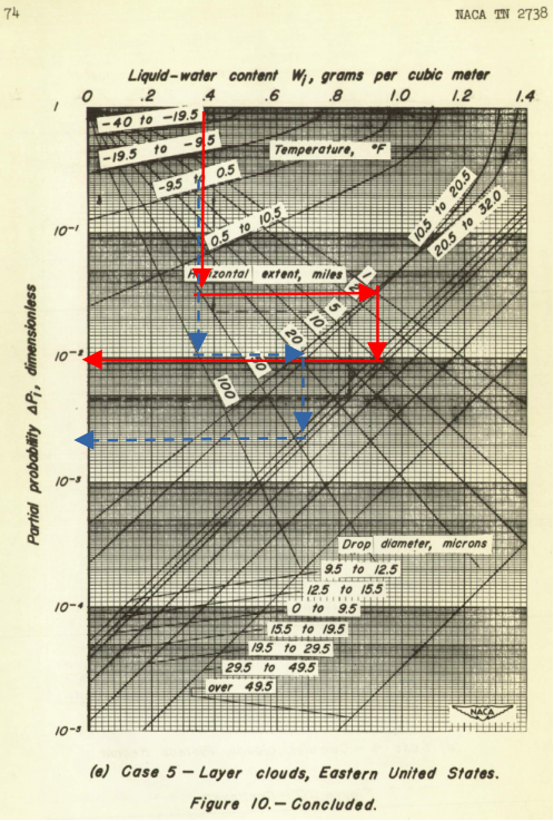
    8-39 figure 10e. Calculations for Flight 8-39.

    Summary

    Calculations are made to assess the probability of encountering certain icing conditions.

    Introduction

    In Porter Perkins Ice Shapes and Ice Protection, references NASA TM 83564 1 and NASA TM 86906 2, the probability of encountering certain icing conditions was assessed, using methods from NACA-TN-2738 3. Here, we will attempt to reproduce those calculations.

    Discussion

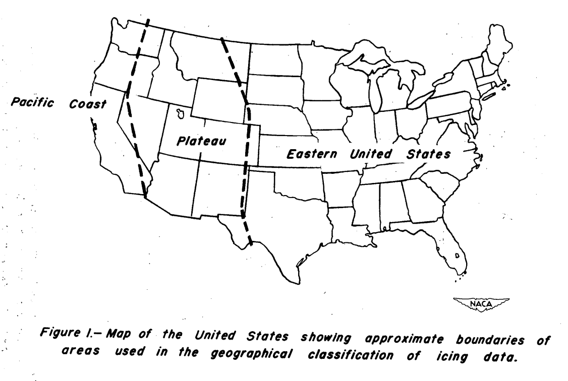
    In NACA-TN-2738, data were divided by geographical region.

    Figure 1. Map of the United States showing approximate 
boundaries of areas used in the geographical classifications 
of icing data.

    The NASA Technical Memos did not state where the natural icing test flights were. However, as three of the authors were based out of the NASA Lewis Research Center, Cleveland, Ohio, I will assume that the flights operated out of there and were in the Eastern United States region.

    So, the appropriate chart to use is Figure …

    read more
  13. Porter Perkins Ice Shapes and Ice Protection

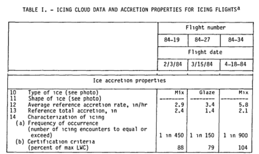
    "An approach to characterizing the severity of an icing encounter is to relate that encounter to the frequency of its occurrence." 1

    Extract from Table I of NASA TM 86906. ICING CLOUD DATA AND ACCRETION PROPERTIES FOR ICING FLIGHTS.

    Introduction

    Three publications with Porter Perkins as an author are included here. Two publications are related, as they cover a flight test campaign to gather detailed ice shape data. The third publication describes a potential improvement to ice protection.

    There is much to see in these publications with multiple authors, and I will focus on what I believe to have been Perkins' contributions.

    Ice Shapes, NASA TM 83564 1 and NASA TM 86906 2

    NASA TM 83564:

    Summary

    This paper deals with the initial results of the NASA Lewis Research Center's flight research in quantifying the performance of an aircraft in various measured icing conditions. Flight research performed in natural icing conditions supports a number of major program elements at NASA. One of these elements is to develop …

    read more
  14. Porter Perkins

    "As the demand for all-weather protection on aircraft for unimpaired and continuous commercial and military service developed, the detrimental effects of ... icing on airplane performance became increasingly important" (1948)

    Figure 1. Tunnel installation of hollow steel air-heated propeller for icing investigation. A tall, lean man with a distinctively tall nose inspects the propeller.

    From NACA-TN-1586. I believe that this is Porter Perkins, circa 1946.

    Summary

    Porter Perkins published on icing topics for over 50 years while at NACA, NASA, and other groups.

    Biographies and Memorials

    Porter J. Perkins is a senior aerospace engineer working in aviation safety as manager of airworthiness of research flight activity at the Lewis Research Center of the U.S. National Aeronautics and Space Administration (NASA), Cleveland, Ohio, U.S. He has specialized in research on aircraft icing for more than 25 years. His in-flight measurements to characterize icing clouds were later incorporated into U.S. icing protection certification standards. He has authored or co-authored more than 25 reports in the field of aircraft icing, and continues to participate in …

    read more
  15. Conclusions of the Ice Protection Thread

    "The industry has now passed through the experimental stages of heating and anti-icing ..." (1946) 1

    Lockheed 12-A. A large, metal construction, low wing, two engine, propeller drive airplane. 
The tail has three vertical fins. Figure 1. Lockheed 12-A airplane. 
Alterations were made to a standard commercial model which include provisions for heating the wings with exhaust gas, and the windshield with heated air.
Figure 12. Three-quarter rear view of airplane, showing location of air discharge louvers in the wing upper surface and exhaust discharge at the wing tip. From NACA-ACR-A-53, 1941.

    Summary

    Ice protection system development continues to address new challenges.

    Key Points

    1. Design guides can lead you to "adequate" designs for several technologies.
    2. Design guides provide procedures to compare candidate systems.
    3. Optimal designs and new requirements may require system development.

    Discussion

    We have seen "the possible methods for overcoming the ice hazard" that were developed in the NACA-era in this Ice Protection Thread. The period up to and through WWII (1945) was largely characterized by expeditious tests to address immediate icing problems.

    The quote above "The industry has now passed through the experimental stages of heating and anti-icing ..." from 1946 was not completely the case, but NACA did move on to more planned scientific and engineering tests and analysis methods development. By the 1950's useful Engineering Design Manuals were available, so that …

    read more
  16. Design Manuals

    Published: Mon 03 April 2023
    Updated: Tue 01 October 2024

    tags: ice protection

    "An aircraft engineer can use this report to design adequate ice protection systems for any type aircraft for any flight mission profile." 1

    Figure 4.2-2. Typical Hot-Air Anti-Icing System.
A diagram of air ducts leading from four engines to manifolds and 
wing ice protection ducts.
    Figure 4.2-2 of ADS-4.

    Summary

    The knowledge of aircraft icing matured to produce engineering design manuals.

    Key Points

    1. NACA publications contributed heavily to later design manuals.
    2. Extensive design publications distilling research into practical methods appeared in the 1950s.
    3. I do not know of a comprehensive design resource for some recent topics such as 3D design and analysis.

    Discussion

    NACA had an early period (up to and including WWII) that was largely characterized by expeditious tests to address immediate icing problems. Later, NACA embarked on more scientifically oriented studies. The science and experience of aircraft ice protection had matured enough by the 1950s for comprehensive engineering design manuals to be written.

    While NACA did not write all of the design manuals, all of the design manuals heavily …

    read more
  17. Thermal Analysis and Surface Wettedness

    Published: Wed 29 March 2023
    Updated: Tue 01 October 2024

    tags: ice protection

    "ice formation can be redefined in more general terms as a thermodynamic problem" 1 (1936)

    Summary

    The thermal analysis of icing conditions has unique challenges, including the determination of heat transfer coefficients and fraction of the surface wetted.

    Key Points

    1. Measured heat transfer coefficients in dry air can be different between flight and tunnel tests, due to free stream turbulence.
    2. Icing conditions tend to promote more turbulent flow on the surface.
    3. Assumptions about the fraction of the surface wetted aft of impingement affect the thermal analysis.

    Introduction

    Experience indicates that certain types of control surfaces, for example, accumulate ice, while others do not. It suggests the need for particular care in the design of slotted controls, the more especially as de-icers can hardly be used in a slot. While of course much of this work can only be done in a refrigerated tunnel where practical tests of actual ice deposit …

    read more
  18. Component Icing

    "I am surprised to find that there are so many details which have not been anticipated before the de-icing tests were started." (1942)

    Figure 1. Typical fuel-vent configuration mounted on NACA 65,2-216 airfoil section in
test section of icing research tunnel.
    Figure 1 from NACA-TN-1789.

    Summary

    The effects of icing on small components must be addressed.

    Key points

    1. Flight tests in natural icing revealed (and still reveal) small component icing effects.
    2. Fuel vents designs were evaluated.
    3. "At present very little is known of the effect of radome icing on radar operation."
    4. The effect of icing on the radome for radar was evaluated.

    Introduction

    We saw some details of the Lewis Rodert's work on the Lockheed 12A test aircraft in Engine Exhaust Heat. However, wing ice protection was not the only challenge:

    To fly into ice clouds and survive, the Ames group necessarily became expert on the impact of ice on the total aircraft. "I am surprised to find", noted [NACA Langley] Engineer-in-Chief Smith DeFrance, "that there are so …

    read more
  19. Windshield Ice Protection

    Published: Mon 06 March 2023
    Updated: Sun 06 October 2024

    tags: ice protection

    "... ice on the airplane windshield, which is known to be a problem in urgent need of solution."

    Figure 14. Sketch based on photographs and flight engineer's notes
of ice accretions on nose and windshields of C-46 airplane after
icing condition 9, table I. Panel angle 60 degrees with the fuselage.
    Figure 14 from NACA-TN-1434.

    Summary

    Ice protection for windshields matured during the NACA-era.

    Key points

    1. In 1939: "The existing practice of making the airplane windshield retractable or removable by the pilot ... against loss of vision due to rain or ice"
    2. By 1947, window heat designs similar to current designs were available.

    Discussion

    Ice protection for windshields matured during the NACA-era.
    Technology progressed from this in 1939 (NACA-SR-130):

    The existing practice of making the airplane windshield retractable or removable by the pilot ... against loss of vision due to rain or ice

    By 1947, there were electrical window heating ice protection designs similar to current designs (NACA-TN-1434).

    "An Investigation of the Prevention of Ice on the Airplane Windshield", NACA-SR-130 1 and NACA-TN-754 2

    INTRODUCTION
    The National Advisory Committee for Aeronautics is conducting a program of …

    read more
  20. Freezing Point Depressant Fluids

    Published: Sun 26 February 2023
    Updated: Tue 01 October 2024

    tags: ice protection

    "Alcohol as a means of protection against ice formation on propeller blades is widely used by commercial air lines on transport airplanes." 1

    Figure 2. A typical propeller alcohol-discharge-nozzle
installation.
    Figure 2 from NACA-RB-4F06.

    Summary

    Freezing point depressant fluids were used widely in the NACA-era.

    Key points

    1. The use of freezing point depressant fluids were not pioneered by NACA, NACA studied improvements.
    2. Analysis methods were developed in the NACA-era.
    3. Freezing point depressant fluids are still used today.

    Discussion

    This is a technology that was not invented by NACA. NACA studies sought to improve the use of freezing point depressant fluids.

    When mixed with water, a freezing point depressant fluids lowers the freezing/melting temperature of the mixture, and enough fluid can lower that temperature below the equilibrium wet surface temperature, preventing or removing ice.

    There are many potential freezing point depressant fluids. In the NACA-era, alcohols were the most widely used. Today, for aircraft deicing on the …

    read more
  21. Combustion heated air and heat transfer coefficients

    Published: Mon 20 February 2023
    Updated: Tue 01 October 2024

    tags: ice protection

    "an effective system for ... wing surfaces to prevent the formation of ice requires knowledge"

    Figure 2 of NACA-ARR-A506
    Figure 2 of NACA-ARR-A506

    Summary

    Combustion heated air, independent of the engines, was used on some aircraft.

    Key Points

    1. Combustion heaters were developed independently of NACA.
    2. 38 NACA publications detail technical aspects of aircraft heaters, including many details on heat exchangers, maturing engineering designs.
    3. Three publications deal with heat transfer for ice protection.

    Discussion

    There were numerous NACA publications on aircraft heaters. For the combustion heaters, air was scooped in, heated by burning aviation gasoline, and used for cabin heating, and wing ice protection on some airplanes (The DC-6, for example).

    Combustion heaters were developed independently of NACA prior to these NACA publications. However, the NACA publications very much detailed the design of not just the heaters, but also associated heat exchangers and components, as well as data needed for analysis (such as "An Investigation of …

    read more
  22. Electrothermal Ice Protection

    "... the power required for ice prevention may be excessive for certain applications, although sufficient power for some degree of ice removal may be provided readily." 1

    Figure 12 from NACA-ARR-4A20. Ice formations on the thermal-electric de-icing
blade shoes installed on a propeller of the XB-17F airplane.
Shoe type: 2
Date: March 27, 1943
Indicated airspeed: 160 mph
Propeller speed: 1010 rpm
Pressure altitude : 10,000 ft 
Total power input: 402 watts for nine minutes
Ambient air temp.: 9 to 11 F
Average unit power: 0.53 watts/sq in.
Type of ice: rime
Unit power to shoe leading edge: 0.79 watts/ sq in.
    Figure 12 of NACA-ARR-4A20.

    Summary

    Electrothermal deicing is studied in the NACA-era.

    Key Points

    1. The power levels required for continuous anti-ice are challenging, so deicing was persued.
    2. Runback ice and residual ice are challenges for deicing.
    3. Analogue computers calculated transient heating and deicing.
    4. A chordwise-sequenced zone heating ice shedding strategy was devised.
    5. The current 787 jet aircraft uses electrothermal heating for wing anti-icing and de-icing.

    Discussion

    The electric powered deicing of propeller blades, as well as wing leading edges, was studied by NACA.

    The deicing of propellers is perhaps easier in some ways, as the centrifugal of the spin greatly aids the shedding of ice. Also, there are scale differences, as a wing airfoil usually has a larger chord length than a propeller. However …

    read more
  23. Compressed Air Heat

    "the most economical icing protection ... consists of a system utilizing hot gas from a convenient heat source, namely, the turbojet-engine compressor" 1

    A jet transport airplane. 
There are many windows in the passenger cabin, implying may rows of seats. 
Notations read: "Shading indicates protected areas", 
which include the wing and empennage leading edges, the engine inlets, 
and forward windshields. 
Figure 1. Theoretical turbojet transport airplane assumed in calculations. 
Gross weight, 125,000 pounds; wing span, 158 feet; wing section, NACA 651-212; 
wing taper, 4:1; cruising speed, 500 miles per hour.
    From NACA-TN-2866.

    Summary

    Compressed air heating becomes common for ice protection in the jet era.

    Key points

    1. To support jet engine powered transportation, NACA had several studies of ice protection using compressed air heating.
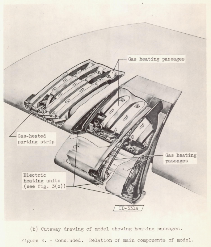
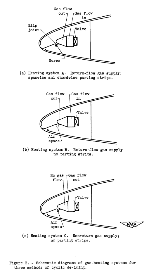
    2. Deicing schemes were proposed to reduce the amount of air bled from the engines.
    3. Some innovative features, like continuously heated parting strips and recirculating hot air supply, did not see much use.
    4. Compressed air heating is used widely today for jet powered transports.

    Discussion

    As aviation entered the jet propulsion age, reciprocating-engine exhaust heat was not an option. However, the jet engine air compressor offers an ample (but not unlimited) supply of hot, compressed air that may be bled from the engine compressor airstream for ice protection, cabin heating, and other functions.

    Several NACA …

    read more
  24. Engine Exhaust Heat

    Published: Mon 06 February 2023
    Updated: Thu 10 October 2024

    tags: ice protection

    "an airplane that will be immune from the dangers of ice accumulation ... is only a matter of technical development." 1

    Figure 24 of NACA-TR-403. A high wing, single engine airplane. A model wing is mounted below the main wing. A water sprays is in from of the model wing.

    Summary

    Practical wing heating designs are developed and proven in natural icing flight tests.

    Key Points

    1. Flight tests were used extensively, as icing wind tunnels were still under development.
    2. Much detailed development over 10 years was required.
    3. "Existing data indicate that sufficient heat is available... the problem is one of distribution".
    4. Design elements were developed that could be used in future compressed air heating.

    Discussion

    NACA-TR-403 1

    This investigation was conducted by the National Advisory Committee for Aeronautics to study the practicability of employing heat as a means of preventing the formation of ice on airplane wings. The report relates essentially to technical problems regarding the extraction of heat from the exhaust gases and it proper distribution over the exposed surfaces. In this connection a separate study has been made …

    read more
  25. Carburetor and Induction Systems

    "A demon was operating the throttle." S. W. Sparrow, 1920. 1

    Figure 3. Schematic diagram of throttle and throttle barrel showing air-flow patterns and throttling ice. A butterfly valve plate angled to allow some airflow past it. Ice is forming on the edges of the valve plate, as well as on the throttle barrel walls downstream of the valve plate, partially obstructing the airflow.
    From NACA-TR-982.

    Summary

    Carburetor icing has been a known hazard for over 100 years, and many protection strategies were studied in the NACA-era.

    Key Points

    1. Carburetor icing has been a known hazard for over 100 years.
    2. Part of the hazard can occur in clear air (throttling icing and fuel-evaporation icing).
    3. "The NACA induction-system icing program at the National Bureau of Standards was initiated in January 1941. The project is financed jointly by the Army, the Navy, and the National Advisory Committee for Aeronautics."
    4. Numerous tests and studies were conducted in the NACA-era.
    5. Many aircraft today have carburetor protection similar to that developed in the NACA-era.

    Discussion

    The spark ignition, Otto cycle engines commonly used on airplanes in the NACA-era typically had carburetors to control the air and fuel entering the cylinders for combustion. These could be affect by ice …

    read more
  26. Deicing boots and ice adhesion

    Published: Mon 30 January 2023
    Updated: Fri 11 October 2024

    tags: ice protection

    "The removal of ice from a De-Icer surface depends on the true adhesion of ice to rubber..." 4

    A drawing of a deicing boot for a wing leading edge. Small tubes in the rubber can be inflated to deform the surface and remove ice.
    Image from “Engineering Summary of Airframe Icing Technical Data” ADS-4, 1963.

    Summary

    Pneumatic boot deicers were the first widely used form of aircraft ice protection, and are still used today.

    Key Points

    1. Deicing boots were developed independent of NACA.
    2. Oil coatings aid the shedding of ice.
    3. NACA development efforts largely shifted to thermal deicing in the 1940s.

    Introduction

    As detailed in "We Freeze to Please": A History of NASA's Icing Research Tunnel and the Quest for Flight Safety, the “expanding rubber sheet” or “ice-removing overshoe” for ice protection was developed independently of NACA in the 1930s, and was the first widely used method of aircraft ice protection. Small passages within the rubber could be periodically inflated to shed ice (typically once every two minutes). While some "inter-cycle" ice forms, the maximum amount …

    read more
  27. Ice Protection

    Published: Sat 28 January 2023
    Updated: Thu 10 October 2024

    tags: ice protection

    "The possible methods for overcoming the ice hazard ..." 1

    Lockheed 12-A. A large, metal construction,
low wing, two engine, propeller drive airplane. 
The tail has three vertical fins. 
Figure 1. Lockheed 12-A airplane. 
Alterations were made to a standard
commercial model which include provisions for heating the
wings with exhaust gas, and the windshield with heated air.
Figure 12. Three-quarter rear view of airplane, showing location
of air discharge louvers in the wing upper surface and
exhaust discharge at the wing tip.
    From NACA-ACR-A-53, 1941. 2

    Summary

    Numerous methods were tested to find effective aircraft ice protection in the NACA-era.

    Introduction

    During the war, more than a hundred cargo planes of the Air Transport Command, flying from bases in India over the Hump to battlefronts in China, crashed in the Himalayas. Most of them were brought down by ice. In a single day in 1944, nine of these big Army transports, loaded with sorely needed supplies for the Allies’ fighting forces, were lost.
    Many of the fatal crashes of commercial aviation have been traced to this same cause. For years commercial transports have been equipped with anti-icing devices, but the apparatus in common use was designed to assist in meeting an emergency when it arises, not to prepare the plane for deliberate flight into ice clouds. If dangerous icing conditions are inadvertently encountered …

    read more
  28. NACA-TN-1472

    "... equations for calculating the rate of heat transfer from airfoils in icing conditions were verified"

    "The Calculation of the Heat Required for Wing Thermal Ice Prevention in Specified Icing Conditions" 1

    Figure 7. Cut-away view of the NACA 652-016 electrically heated airfoil model
showing construction details.

    Summary

    Natural icing flight tests with an instrumented test airfoil are compared to 2D thermodynamic calculations.

    Key points

    1. Thermodynamic equations for a heated surface with water impingement are detailed.
    2. Test flights in natural icing conditions measured surface temperature for a heated surface.
    3. Runback water characteristics were noted.
    4. Heat transfer coefficients in icing were be inferred from measurements and calculations.
    5. "the design of heated wings on a fundamental, wet-air basis now can be undertaken with reasonable certainty."

    Abstract

    As a result of a fundamental investigation of the meteorological conditions conducive to the formation of ice on aircraft and a study of the process of airfoil thermal ice prevention, previously derived equations for calculating the rate of heat transfer from airfoils …

    read more
  29. NACA-TR-831

    "It has been shown that the temperature of the surface of the wing in conditions of icing can be predicted with considerable exactitude from the temperatures measured in clear air."

    "An Analysis of the Dissipation of Heat in Conditions of Icing from a Section of the Wing of the C-46 Airplane" 1

    Figure 2. Measured temperatures at wing station 159 during flight in C-46 airplane.

    Summary

    Two-dimensional heat balance equations for ice protection are detailed.

    Key points

    1. Heat balance equations for ice protection are detailed.
    2. An assumption about water drop temperature approaching an object is made.
    3. A cylinder approximation for an airfoil leading edge is used for water drop impingement.

    Abstract

    A method is given for calculating the temperature that a surface, heated internally by air, will assume in specified conditions of icing. The method can be applied generally to predict the performance, under conditions of icing, of the thermal system for protecting aircraft. Calculations have been made for a section of the …

    read more