"Experience has shown that ... the inlet guide vanes of an axial-flow turbojet engine constitute the most critical component to be protected from icing"
"Investigation of Power Requirements for Ice Prevention and Cyclical De-Icing of Inlet Guide Vanes with Internal Electric Heaters" 1
Abstract
An investigation was conducted to determine the electric power requirements necessary for ice protection of inlet guide vanes by continuous heating and by cyclical de-icing. Data are presented to show the effect of ambient-air temperature, liquid-water content, air velocity, heat-on period, and cycle times on the power requirements for these two methods of ice protection.
The results showed that for a hypothetical engine using 28 inlet guide vanes under similar icing conditions, cyclical de-icing can provide a total power saving as high as 79 percent over that required for continuous heating. Heat-on periods in the order of 10 seconds with a cycle ratio of about 1:7 resulted in the best over-all performance with respect to total power requirements and aerodynamic losses during the heat-off period.
Power requirements reported herein may be reduced by as much as 25 percent by achieving a more uniform surface-temperature distribution. A parameter in terma of engine mass flow, vane size, vane surface temperature, and the icing conditions ahead of the inlet guide vanes was developed by which an extension of the experimental data to icing conditions and inlet guide vanes, other than those investigated was possible.
Discussion
INTRODUCTION
The desirability for all-weather operation of turbojet aircraft has necessitated extensive research on methods of icing protection for the various engine components. Experience has shown that, in the absence of a compressor-inlet screen, the inlet guide vanes of an axial-flow turbojet engine constitute the most critical component to be protected from icing. Ice formations on the inlet guide vanes seriously affect engine performance by decreasing the compressor efficiency, by reducing the mass flow through the engine, and by causing large pressure losses at the compressor inlet. These factors, which reduce the net thrust, increase the specific fuel consumption, and increase the tail-pipe temperatures beyond safe operation limits, can render the engine inoperative in a matter of minutes in a heavy icing condition.
Icing in the initial stages of compressor blading in current engines is deemed of secondary importance to inlet-guide-vane icing because icing occurs principally on the leading edges, where ice formations are limited in size by mechanical abrasion due to the close spacing and relative motion between the rotor- and the stator-blade rows.
Ice formations on inlet guide vanes tend to increase rapidly in size at ambient-air temperatures above 10° F. In the temperature range of 10° to 32° F, the ice formations at the leading and the trailing edges tend to mushroom and if the vanes are closely spaced, bridging of the ice formations between adjacent vanes occurs. By use of larger size inlet guide vanes with a greater spacing between vanes, ice bridging between adjacent vanes can be considerably delayed and the icing tolerance of the engine increased. The icing protection of inlet guide vanes may be accomplished by heating the surface of the vanes either by use of hot gas or by electrical means.
An investigation at the NACA Levis laboratory to determine the electric power requirements for inlet-guide-vane icing protection was conducted on vanes that were twice the size of vanes in current production engines. The increased size was required to provide for adequate instrumentation and is in accordance with current design trends. The investigation was made over a range of icing conditions to determine the minimum electric power requirements for icing protection by continuous heating of the inlet guide vanes. In addition, cyclical de-icing studies were made to determine the possible saving in total power by this system of ice protection over the power required for continuous heating. An analysis is included to extend the experimental results to vane sizes and icing conditions other than those studied.
APPARATUS AND INSTRUMENTATION
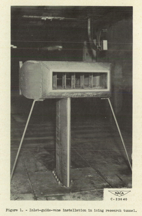
The electrically heated guide vane was the center vane of a cascade of five vanes mounted in a special housing in the 6- by 9-foot test section of the icing research tunnel (fig. 1). The walls of the housing end the two guide vanes at each side of the center vane were hollow and gas-heated to prevent icing. The air flow through the housing was regulated by remotely controlled flaps at the exit of the housing.
Each vane had a chord of 2.37 inches and a total span of 6.12 inches, of which 5.90 Inches were exposed between the upper and lover walls of the housing. The spacing between vanes was 3.12 inches. Only the electrically heated vane was aluminum with heating elements and guide tubes for thermocouples cast in place. The heating element consisted of Nichrome wire encased in glass-cloth insulation and covered with a copper sheath; the element was in the shape of a hairpin so that both ends emerged from the top of the vane. Four heater circuits were used in the vane investigated and were spaced as shown in figure 2. Each circuit was independently connected to a variable transformer, which permitted selective power input to the four circuits. Power input to the various circuits was measured with a recording wattmeter. An electronic timer was used. to regulate the heat-on and heat-off periods for the cyclical de-icing studies. Stainless-steel pilot tubes were positioned in the vane at the time of casting so that thermocouple wires could be inserted. Iron-constantan thermocouples were used and the junction peened flush with the vane surface. The thermocouples were positioned in a chordwise plane (fig. 2) 3 inches from the top of the vane.
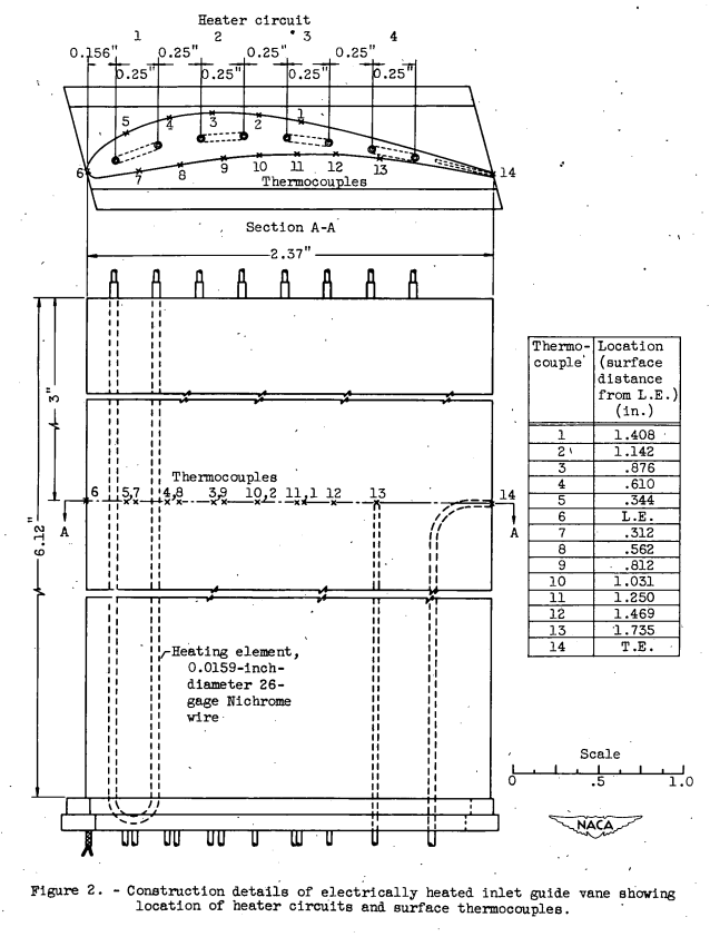
Note the "iron-constantan thermocouples were used and the junction peened flush with the vane surface". The peening (sometimes perform using the ball-peen end of a hammer, other times with metal shot propelled like sand-blasting) ensures that the thermocouple is encased in the metal surface where the temperature is intended to be read. I have seen large thermocouple errors with other installation methods (particularly using adhesives, including "thermally conductive" adhesives) where the reported temperature is obviously not the actual surface temperature.
Wet-air heat-transfer evaluation. - In order to obtain an understanding of the heat-transfer mechanism for icing conditions, analysis was made to determine the wet-air heat-transfer coefficients HX+M in terms of local power densities. The analysis used to obtain these coefficients makes use of, the wet-air analysis presented in reference 2.
The heat loss from the inlet guide vane caused by evaporation was calculated using Hardy's evaporation factor as given in reference 4. The full evaporation factor was used on all surfaces subject to direct water impingement as indicated by the values in figure 6(b).
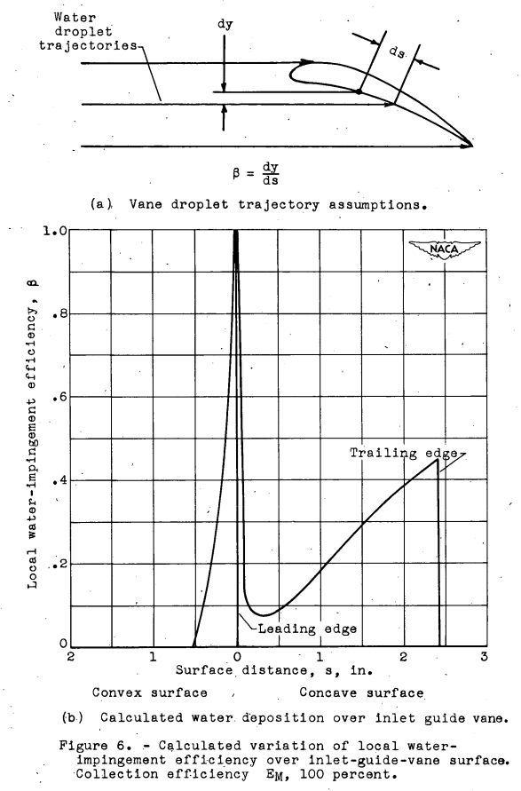
Beyond the limit of water impingement on the convex surface, runback was assumed to occur and, based on experimental observations of airfoil sections, an average value of 20 percent of the full evaporation factor was assumed. As in the dry-air analysis, the vane-surface temperatures were maintained as uniform as possible at the minimum total power required to prevent icing. The surface temperatures for two typical cases analyzed are shown. In figure 7. The icing conditions for these temperature distributions were: air velocities of 401 and 261 feet per second, ambient-alr temperatures of -12° and -5° F, liquid-water contents of 0.58 and 0.62 gram per cubic meter, and average experimental power densities of 9.3 and 6.4 watts per square inch, respectively.
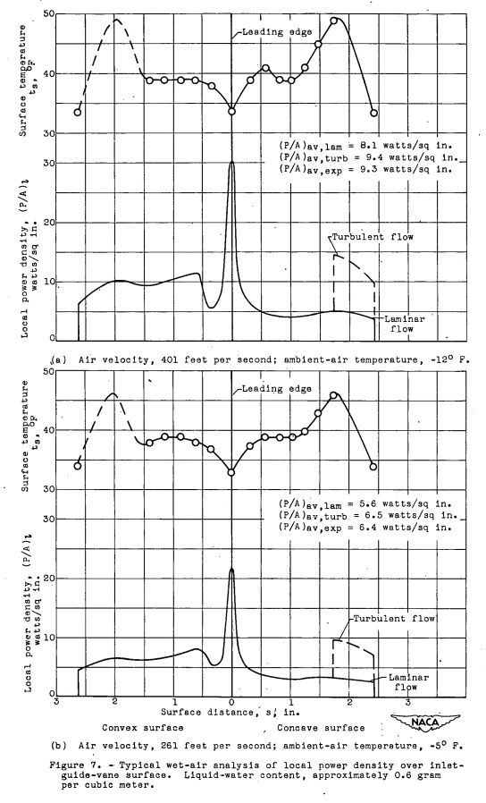
The same boundary-layer conditions as for the dry-air analysis were initially assumed. Calculations of the local power density as a function of the surface distance were then made (fig. 7) for the icing conditions previously stated. Integration, of the area under the curves shown in figure 7 indicated lover total power inputs for icing protection of the vane than were experimentally obtained. The boundary layer assumed on the concave surface was therefore changed to Include a turbulent boundary layer over the rearward portion of the inlet guide vane as shown in figure 7. By an adjustment of the amount of vane area assumed to be in the turbulent-flow region, the calculated average value of power density or average wet-air heat-transfer coefficient could be calculated to approach the experimentally obtained average value. The validity of the assumption of a partially turbulent boundary layer on the concave surface has been substantiated In reference 2 and at the Lewis laboratory by unpublished experimental studies of heat transfer from an airfoil in icing conditions, which indicate that a water film on the surface of an airfoil section causes early transition from laminar to turbulent flow.
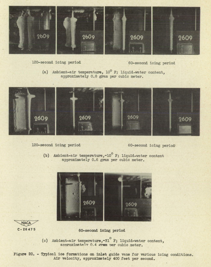
With respect to cyclical de-icing, a short heat-off period of about 60 seconds therefore appears to be more desirable than longer periods in the order of 120 seconds. Photographs of typical ice formations on an inlet guide vane are shown in figure 20 for an air velocity of 400 feet. per second. The icing conditions for the ice formations shown in these photographs were a liquid-water content ranging from 0.4 to 0.85 gram per cubic meter with ambient-air temperatures ranging from 310 to 100 F. The large ice formations on the leading and trailing edges for the 120-second icing period were similar to those causing the large pressure losses shown in figure 19. These losses were primarily caused by the reduction in the free flow area by the ice formations between adjacent vanes.

Conclusions
SUMMARY OF RESULTS
From a study of the electric power requirements necessary for ice protection of inlet guide vanes by continuous heating and by cyclical de-icing, the following results were obtained:
1. The average power requirement per inlet guide vane per cycle is in the order of 79 percent less than that required for continuous heat- ing under the same conditions: namely, air velocity ahead of the vane, 400 feet per second; ambient-air temperature, _1l0 F; liquid-water content, approximately 0.6 gram per cubic meter; heat-on time, 10 sec- onds; and. cycle ratio 1:7.
2. Cycle periods of 10 or less seconds heat-on and 60 seconds. heat-off result in the best over-all performance with respect to total power input required. for icing protection and aerodynamic losses during the heat-off period.
3. For conditions similar to those given in the first result, the electric power requirements for a hypothetical engine utilizing continuous heating for the 28 inlet guide vanes with a total vane area of 865 square inches was 7800 watts (9.0 watts/sq in.), whereas under the same conditions cyclical de-icing require4 only 1650 watts. Because a uniform surface temperature could not be fully attained on the Inlet guide vane investigated, the continuous requirement is approximately 25 percent higher than would be required for a uniform surface temperature of 32° F.
4. A parameter was developed in terms of the engine mass flow, vane size, ambient pressure and temperature ahead of the inlet, guide vanes, surface temperature, and liquid-water content that permits a determination of power requirements for ice prevention beyond the limits of the experimental studies. The experimental values of power required for Ice prevention of inlet guide vanes coincide closely with values calculated using this parameter.
Citations
NACA-RM-E50H29 is cited eight times, per scholar.google.com.
Related
This is part of the Engine Inlet Icing Thread.
Notes
-
von Glahn, Uwe H., and Blatz, Robert E.: Investigation of Power Requirements for Ice Prevention and Cyclical De-Icing of Inlet Guide Vanes with Internal Electric Heaters. NACA-RM-E50H29, Dec. 1950. ntrs.nasa.gov ↩