"This criterion, unavoidably subjective in nature, caused considerable scatter in the data"
"Heat Requirements for Ice Protection of a Cyclically Gas-Heated, 36° Swept Airfoil with Partial-Span Leading-Edge Slat" 1
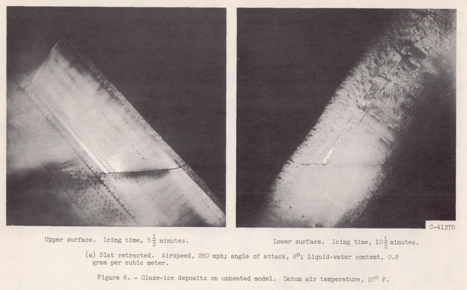
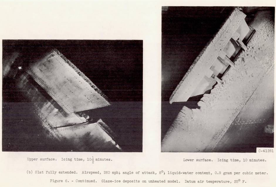
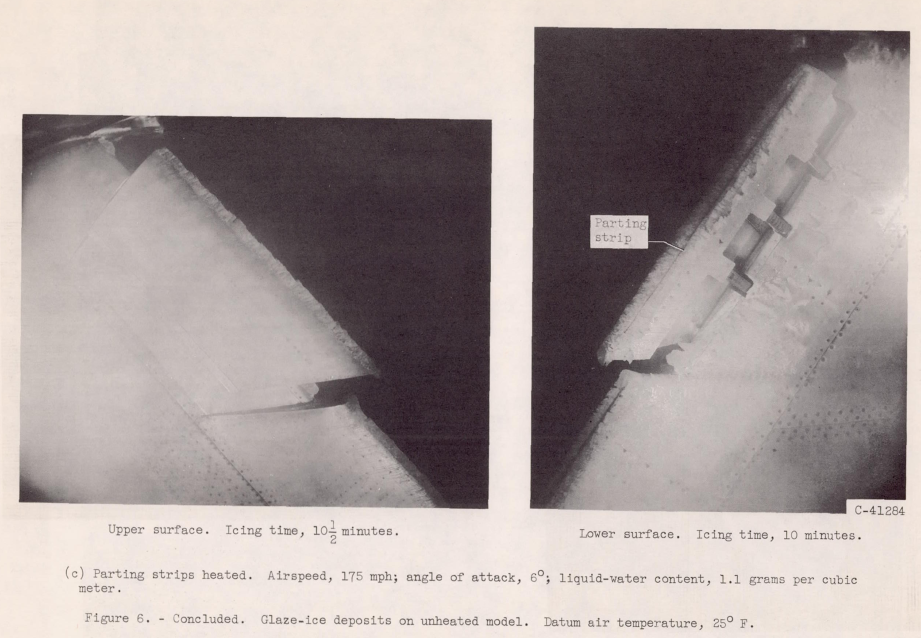
SUMMARY
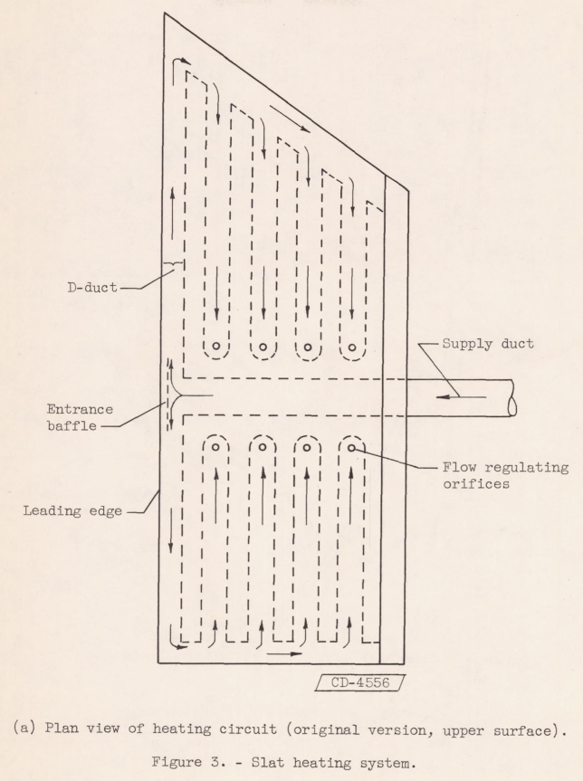
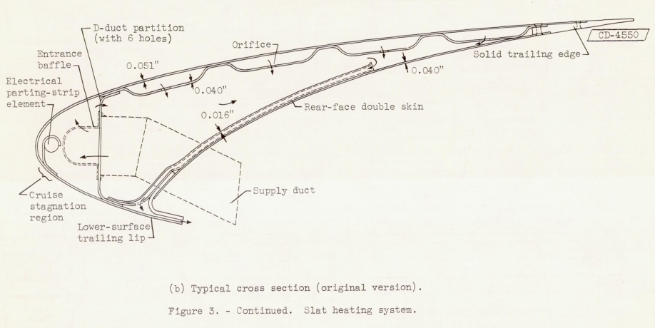
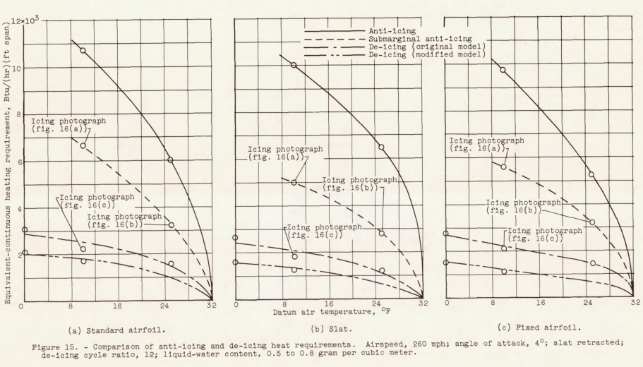
Heating requirements for satisfactory cyclic de-icing over a wide range of icing and operating conditions have been determined for a gas-heated, 36° swept airfoil of 6.9-foot chord with a partial-span leading-edge slat. Comparisons of heating requirements and effectiveness were made between the slatted and unslatted portions of the airfoil. Studies were also made comparing cyclic de-icing with continuous anti-icing, and cyclic de-icing systems with and without leading-edge ice-free parting strips. De-icing heat requirements were approximately the same with either heated or unheated parting strips because of the aerodynamic effects of the 36° sweep angle and the spanwise saw-tooth profile of leading-edge glaze-ice deposits. Cyclic de-icing heat-source requirements were found to be one-fourth or less of the heat requirements for complete anti-icing. The primary factors that affected the performance of the cyclic de-icing heating system were ambient air temperature, heat distribution, and thermel lag.
Discussion
In addition to icing on a highly swept wing, this publication illustrates methods of ice protection for a moving leading-edge slat. Cyclic de-icing versus anti-icing is also covered.
We also see the challenges of developing performance requirements for cyclic de-icing.
INTRODUCTION
The NACA Lewis laboratory has studied several hot-gas icing protection systems in order to obtain data useful in the design of such systems (refs. 1 to 4). In some of these studies, the technique of cyclic deicing was investigated to determine the heat-flow savings that result from intermittent heating of a portion of an airfoil surface subject to icing as compared with continuous heating of the surface. In evaluating the heat-flow savings resulting from cyclic de-icing, the airfoil drag caused by the ice formations that accrue on the surfaces between heating periods must be considered. The drag penalties for several airfoil shapes and ice-protection techniques have already been obtained (refs. 3, 5, 6, and 7), including the drag study (ref. 5) of the airfoil model used in the present investigation.
In the present study, the heat requirements and effectiveness of a hot-gas cyclic de-icing system in a 360-swept-airfoil model with a leading-edge slat have been investigated. The model utilized an NACA 634-009 airfoil section with a slatted leading edge over only a portion of the span. This feature was incorporated to compare simultaneously the heating and icing characteristics of the slatted section with those of the unslatted airfoil. The model was provided also with both hot gas and electrically heated strips along the leading edges in order to determine the effect of continuously heated ice-free parting strips on deicing performance.
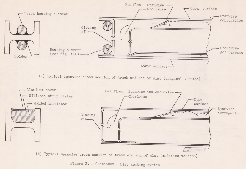
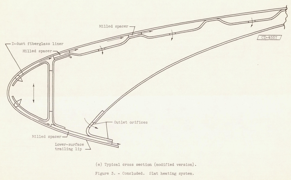
The airfoil model was studied over a range of icing conditions in the NACA Lewis laboratory icing tunnel. Ice-removal data were obtained for the swept-back model, and a study was made of the special problems associated with de-icing of a movable leading-edge slat. The model, furnished by an aircraft manufacturer, was the first hot-gas cyclic de-icing system to be developed for production. In an effort to correct some heating deficiencies that became evident during the tests, modifications of the original internal heating arrangements were made, and limited data on the over-all effects of these changes were obtained.
MODEL AND EQUIPMENT
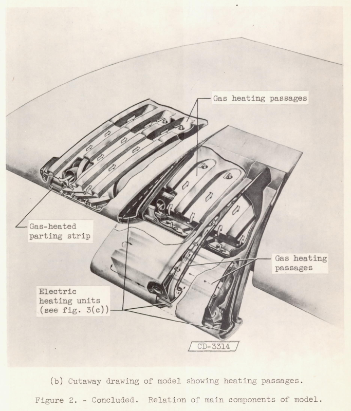
The model used in this study (fig. 1) is a constant-section NACA 63A-009 airfoil which spans the 6-foot height of the icing research tunnel. The leading and trailing edges of the model are swept back at an angle of 36° to the airstream. The airfoil structure and heating passages were constructed either perpendicular or parallel to the leading edge. However, in this report, chordwise dimensions will be taken parallel to the airstream and spanwise dimensions parallel to the lead-ing edge. The streamwise airfoil chord was 6.9 feet.
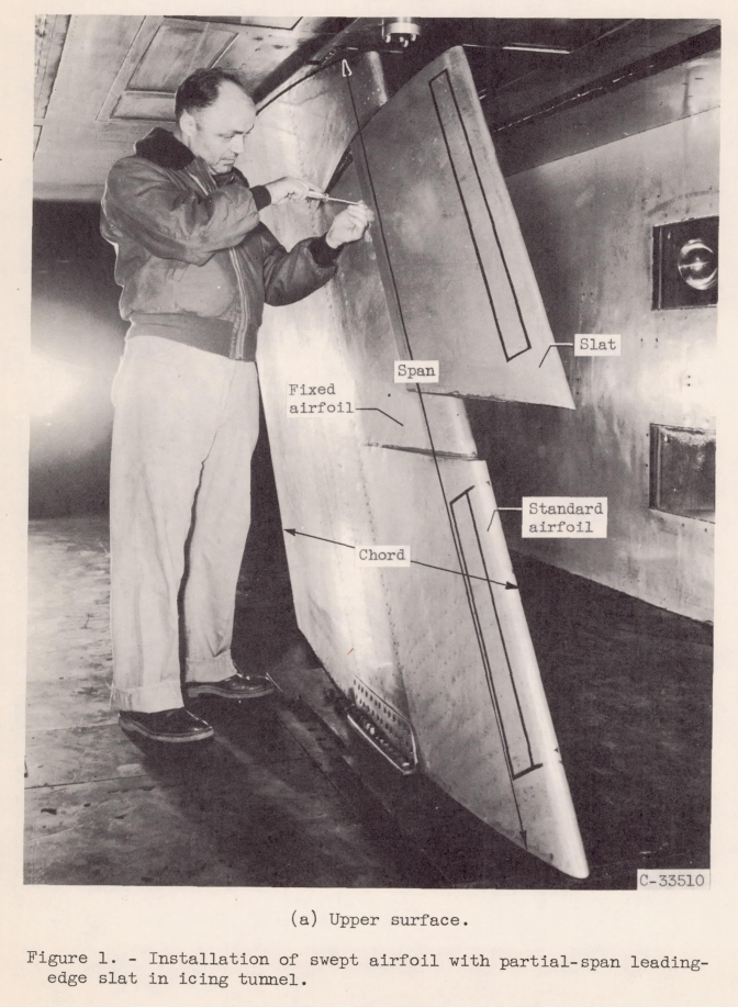
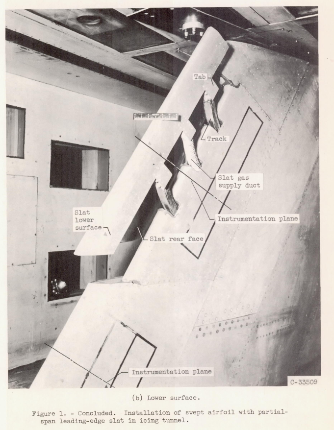
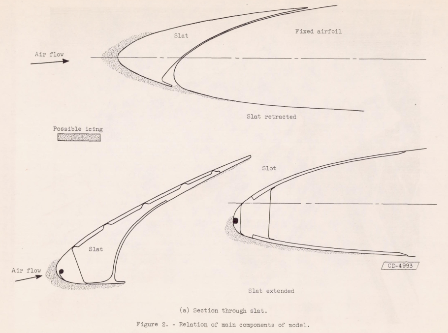
The airfoil leading-edge section consists of two main parts: an unslatted or "standard-airfoil" section with a spanwise extent of approximately 26 inches and a slatted leading-edge section with a spanwise extent of 44 inches. The relation of the movable slat to the fixed-airfoil section behind the slat is shown in figure 2. Slat extension is normally associated with large angles of attack.
Slat
The leading-edge slat has a 20-inch chord in the streamwise direction (fig. 1(a)). The slat moves forward on tracks and rollers into the airstream in a direction normal to the leading edge. For the tests, a hydraulic system moves and holds the slat in any desired forward position. The slat tracks are curved so that the extended slat moves on a circular arc to positions forward of and below the lower surface of the fixed-airfoil section (fig. 2(a)). The radius of curvature of the tracks 1s approximately 34 inches, and the full movement of the slat is over a 16° central angle.

CONDITIONS AND PROCEDURE
Range of Conditions
The geometric angle of attack of the airfoil was varied from 0° to 8° with the slat fully retracted; with the slat extended 8° (half of maximum travel), the angle of attack for the airfoil was set at 8°. A study was also made at an angle of attack of 12° with the slat half extended (8°) and fully extended (16°). The studies with slat extended were made at an airspeed of 175 mph.
Procedure for Obtaining Data
In obtaining data during a de-icing run, the procedure was to establish first the tunnel conditions of airspeed and air temperature and then the heating conditions of both gas flow and gas temperature (at the cycling valves). The gas flows were stabilized while the cycling valves were positioned to dump the gas flow into the tunnel. Then, water sprays were turned on and the cycle timers were started simultaneously to control selected icing and heating periods. Generally, the first cycle started with the icing period and followed with the heating (de-icing) period.
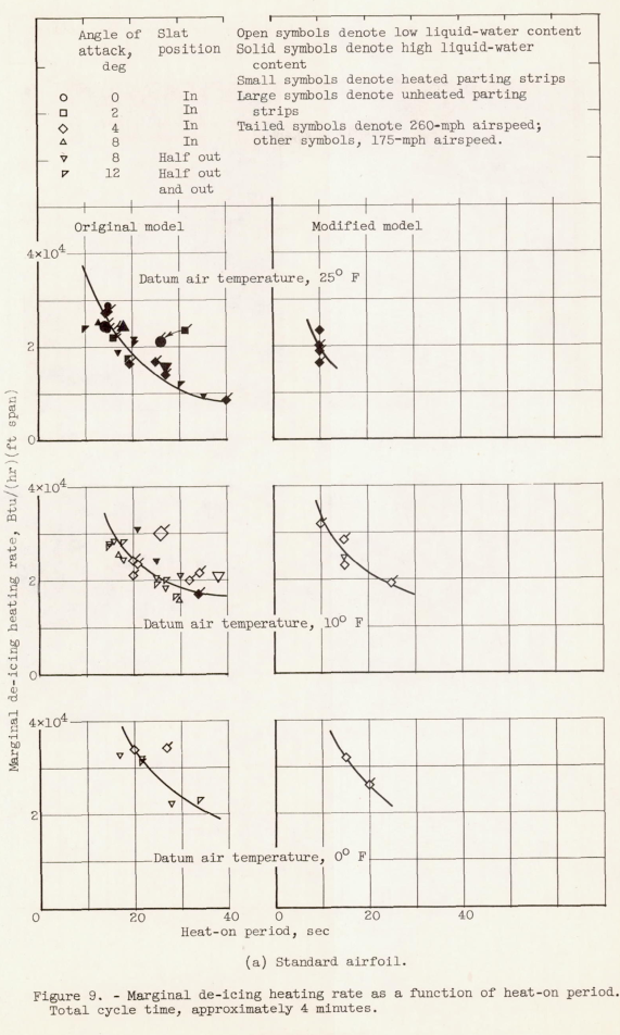
In order to determine heating requirements, the first few icing cycles were utilized to adjust the heating rates until satisfactory deicing was obtained, For convenience, the heat-on times were adjusted (with other conditions constant) until satisfactory ice shedding performance was obtained.
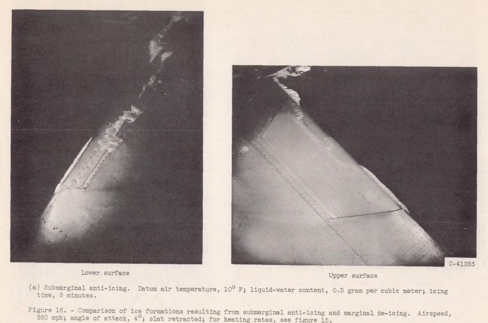
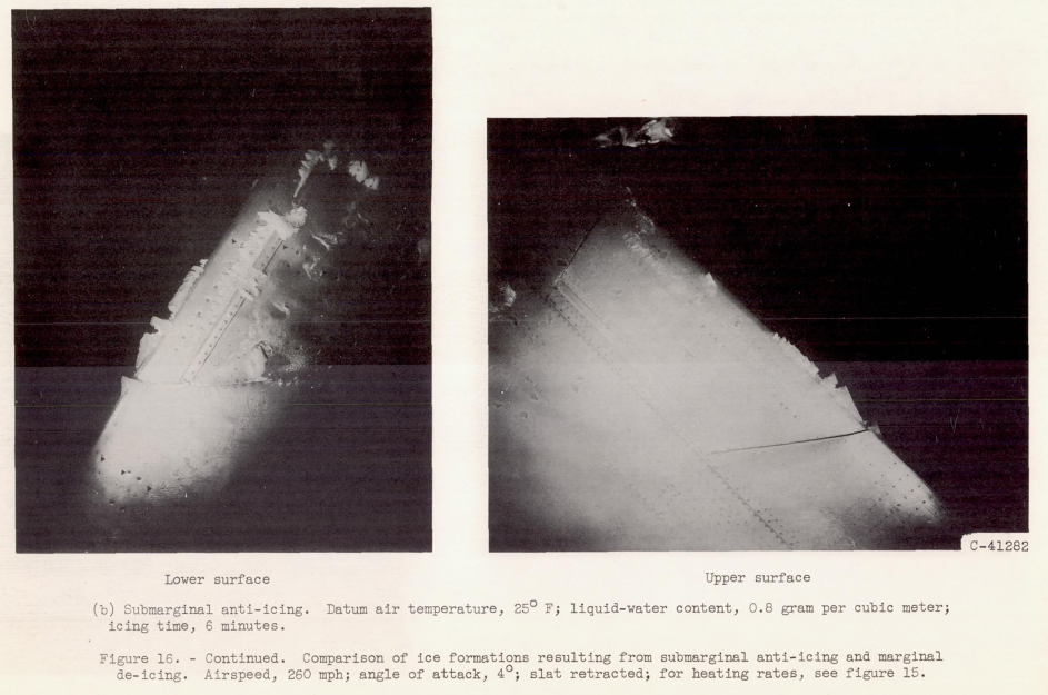
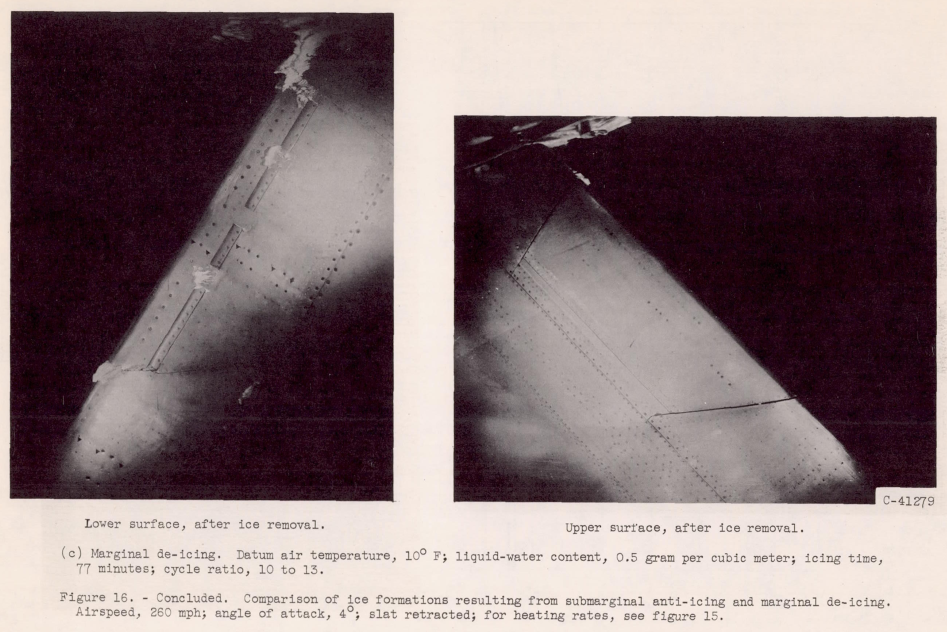
Satisfactory de-icing performance was determined by visual observation and then the model was photographed at significant moments in the cycle. The criterion of satisfactory, or marginal, de-icing was selected as the condition of complete ice removal from an airfoil section as far aft as the limit of the heatable double skin. This criterion was compromised in certain local areas that were inadequately heated, and consequently, some ice formations which were local in nature would not shed and were ignored as much as possible in establishing marginal levels of heating. This criterion, unavoidably subjective in nature, caused considerable scatter in the data.
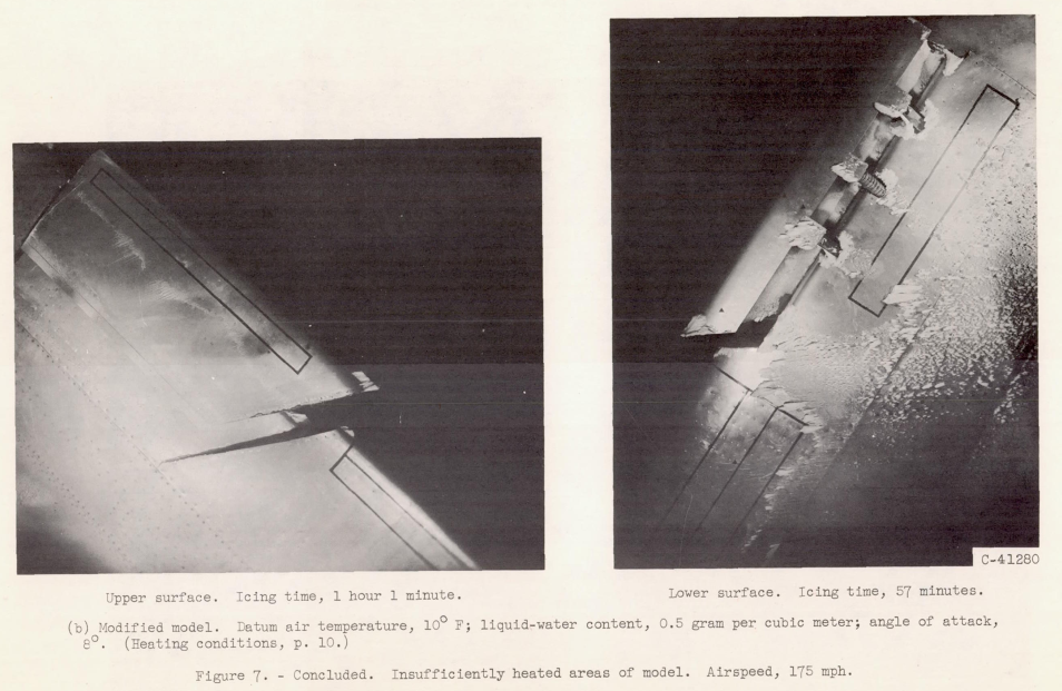
There are 23 figures in NACA-RM-E56B23, many of them with multiple parts. Selected images are included here.
Conclusions
Heating requirements for satisfactory cyclic de-icing were obtained over a wide range of icing and operating conditions for a slat and a standard-airfoil section with and without leading-edge ice-free parting strips. For the models and conditions studied, the following principal results were obtained:
1. Cyclic de-icing was compared with anti-icing and found to require about 25 percent or less of the heat source required for complete anti-icing.
2. De-icing heat requirements were approximately the same with either heated or unheated parting strips. This resulted from the spanwise flow component associated with swept wings, which helped remove ice by blowing parallel to the leading edge and which also caused leading-edge glaze ice to form in discontinuous spanwise saw-tooth pieces that broke up and shed readily without need of a parting strip.
3. Cyclic de-icing heat requirements increase markedly with decrease in the datum air temperature. Negligible or inconsistent effects on heat requirements were found for the following variables: angle of attack, slat position, airspeed, and liquid-water content. An increase in heating rates was required with an increase in the icing period of the cycle.
4. The heating time required to shed ice formations near the lead-ing edge was several seconds longer than that required to elevate the surface temperatures to 32° F. Toward the aft end of the heated area, the ice shed when surface temperatures were close to 32° F. At high rates of heating, the ice would tend to shed almost simultaneously over the whole heated lower surface of the standard airfoil.
5. Several localized areas of the model were extremely slow in shedding ice because of insufficient heating at these points. Most of these deficiencies were attributed to the structural complexity inherent with leading-edge slats and illustrate the need for providing uniform surface-temperatures over the model during the heating period.
6. The modified version of the model, without parting strips and with improved insulation and flow distribution, required less heat-source capacity than the original version by about 40 percent. The cyclic heat-source requirements of the unswept gas-heated, 12-percent-thick airfoil of reference 2 were approximately between the requirements of the present original and modified models. More uniform surface-temperatures and smaller D-duct gas-temperature losses were obtained with the modified model than with the original version.
I have seen the effect noted in Result 5 in many tests. Ice may not shed until all areas of potential adherence have melted.
Note also [emphasis added]:
Satisfactory de-icing performance was determined by visual observation and then the model was photographed at significant moments in the cycle. The criterion of satisfactory, or marginal, de-icing was selected as the condition of complete ice removal from an airfoil section as far aft as the limit of the heatable double skin. This criterion was compromised in certain local areas that were inadequately heated, and consequently, some ice formations which were local in nature would not shed and were ignored as much as possible in establishing marginal levels of heating. This criterion, unavoidably subjective in nature, caused considerable scatter in the data.
A difficult part of using cyclical deicing is determining criteria for acceptable performance. In NACA-RM-E56B23, the criteria was "unavoidably subjective in nature". There is a lot of engineering judgment in determining this, and subsequent test data might require revising the judgment. What was ignored may turn out to be an important factor.
Citations
NACA-RM-E56B23 is cited two times per scholar.google.com.
Notes
-
Gray, Vernon H., and von Glahn, Uwe H.: Heat Requirements for Ice Protection of a Cyclically Gas-Heated, 36 Swept Airfoil with Partial-Span Leading-Edge Slat. NACA-RM-E56B23, 1956. ntrs.nasa.gov ↩