"Serious icing of a turbojet-engine installation may render the engine inoperative in a matter of minutes."
"NACA Investigations of Icing-Protection Systems for Turbojet-Engine Installations" 1
Abstract
Investigations have been made in flight and in wind tunnels tc determine which components of turbojet installations are most critical in icing conditions, and to evaluate several methods of icing protection. From these studies, the requirements necessary for adequate icing protection and the consequent penalties on engine performance can be estimated.
Because investigations have indicated that the compressor-inlet screen constitutes the greatest icing hazard and is difficult to protect, complete removal or retraction of the screen upon encountering an icing condition is recommended. In the absence of the screen, the inlet guide vanes of an axial-flow-type turbojet engine constitute the greatest danger to engine operation in an icing condition; a centrifugal- type engine, on the other hand, is relatively unsusceptible to icing once the screen has been removed.
Of the three icing-protection systems investigated, surface heat- ing, hot-gas bleedback, and inertia-separation inlets, only the first two offer an acceptable solution to the problem of engine icing protection. Surface heating, either by gas heating or electrical means, appears to be the most acceptable icing-protection method with regard to performance losses. Hot-gas bleedback, although causing undesirable thrust losses, offers an easy means of obtaining icing protection for some installations. The final choice of an icing-protection system depends, however, on the supply of heated gas and electrical power available and on the allowable performance and. weight penalties associated with each system.
Discussion
As this publication is long (78 pages), this review will focus mostly on the configuration descriptions and conclusions, and less on specific test results. There is much more detail available in the original publication.
INTRODUCTION
The development of high-performance turbojet engines and the advent of all-weather turbojet-propelled aircraft have necessitated extensive research programs to determine methods for icing protection of the various components of such engine installations. Not only is the inlet ducting of a turbojet-engine installation subject to icing, but, more important, the internal elements such as the compressor-inlet screen, the inlet guide vanes, and the compressor blading are also subject to icing. Ice formations on the internal elements seriously affect the operation and the performance characteristics of a turbojet engine. The ice formations on the screen and the inlet guide vanes reduce the compressor-inlet area and increase the pressure losses. In addition, ice formations on the compressor blading may decrease the compressor efficiency and thus further reduce the pressure available in the engine. The over-all pressure and mass-flow losses of the entire turbojet-engine installation markedly decrease the propulsive thrust, particularly at high flight Mach numbers (reference 1). Serious icing of a turbojet-engine installation may render the engine inoperative in a matter of minutes.
The scope of NACA turbojet-engine icing investigations to date has been threefold: (1) to study the effect of icing on turbojet-engine performance, (2) to evaluate the feasibility and the practicability of several methods for protecting turbojet engines from icing, and (3) to determine the effects of these ice-protection methods on engine performance under both dry and icing conditions. The investigations were carried out at the NACA Lewis laboratory in natural-flight icing conditions and under simulated icing conditions using a water-spray system in the altitude wind tunnel and the icing research tunnel.
The icing investigations in natural-flight icing conditions were confined to the determination of the effect of icing on turbojet-engine performance. Investigations in the altitude wind tunnel included the three phases of icing investigations previously mentioned. Studies in the icing research tunnel were primarily concerned with several methods of ice protection for turbojet-engine inlets and an evaluation of the effects of these methods on engine performance.
Three basic methods have been advanced for the icing protection of turbojet engines:
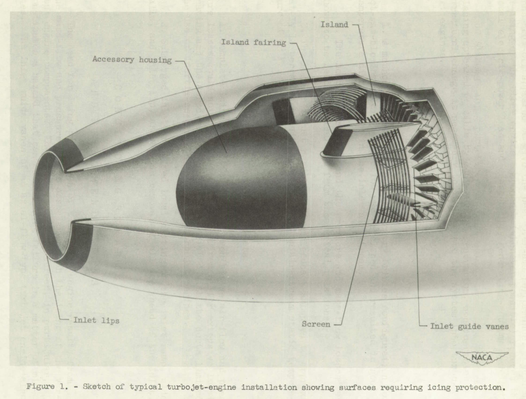
(1) Local heating of all surfaces subject to icing (fig. 1). Surface heating may be accomplished by
(a) passing heated gases through passages within the component walls, (b) internal or external electrical heating pads or films, and (c) electrical eddy currents induced by a pulsating magnetic field in the elements to be protected.
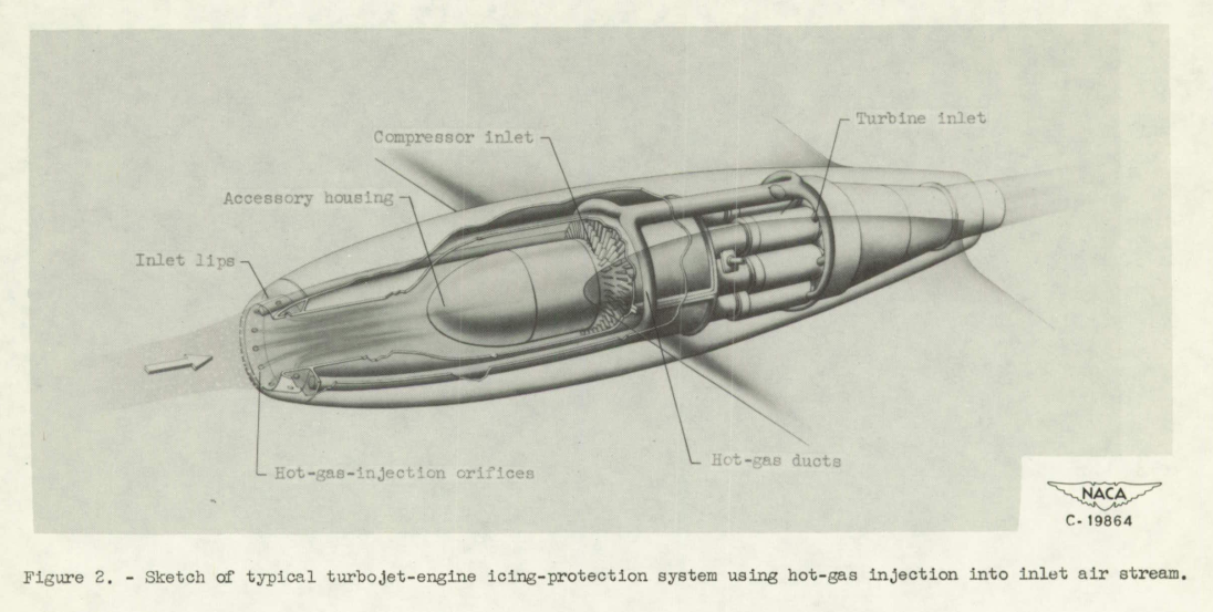
(2) Addition of heat to the entire mass of air passing through the inlet (fig. 2), which raises the inlet-air temperature above freezing. By injecting hot gas into the air stream at the inlet, the engine and most components in the inlet duct are afforded icing protection in one operation.
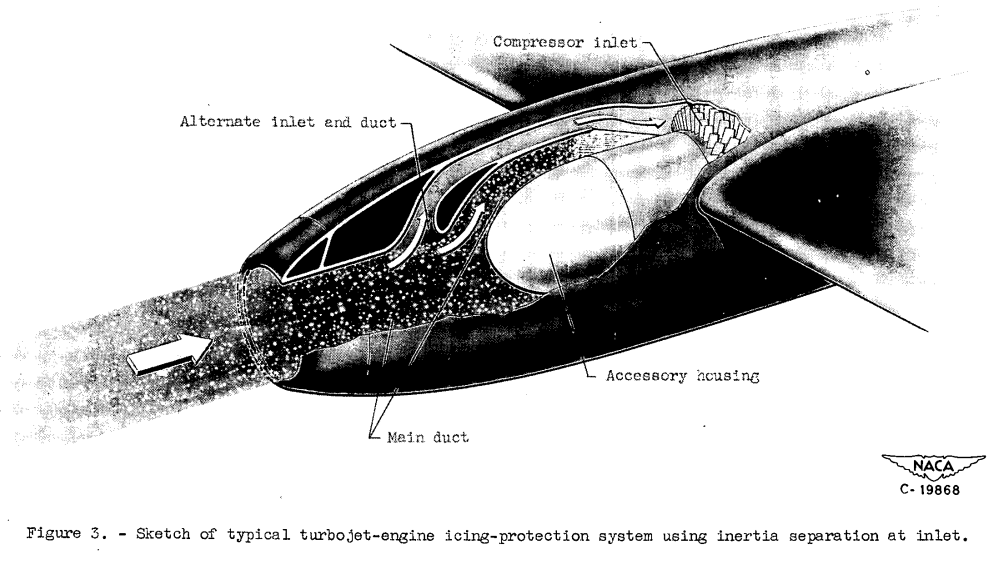
(3) Inertia separation of supercooled water droplets out of the engine-inlet air stream by special inlet and duct design (fig. 3). The duct design consists of a single inlet opening followed by a main duct for nonicing operation and an alternate duct with sharply curved passages through which air, with a greatly reduced water content in an icing condition, can pass to the compressor inlet.
A summary based on the collective results of all NACA investigations to date on turbojet-engine ice protection is presented herein.
EXPERIMENTAL TECHNIQUES
Icing investigations of turbojet engines and inlets were conducted at the NACA Lewis laboratory in the following three phases:
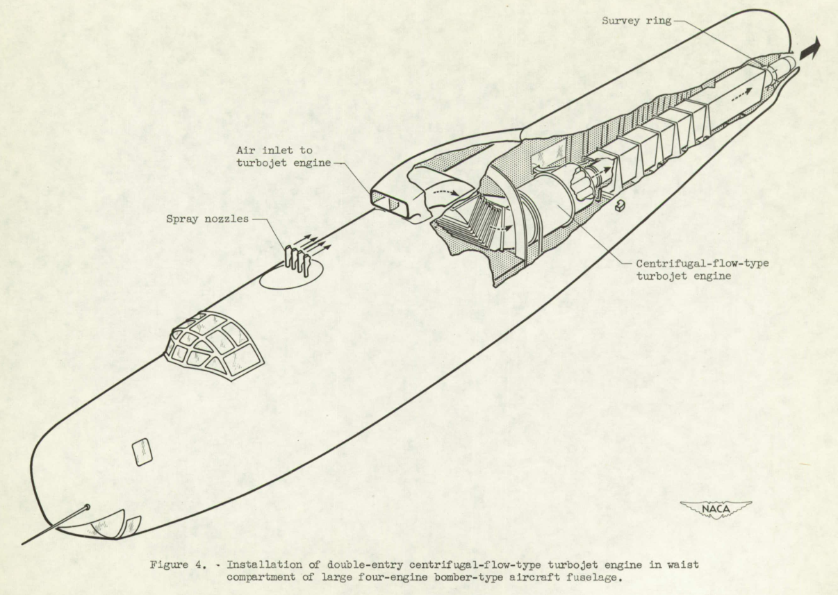
Flight. - Two flight investigations of the effect of icing on turbojet engines were conducted, one using a centrifugal-flow-type engine and the other using an axial-flow-type engine. In the first flight investigation (unpublished), a centrifugal-flow-type turbojet engine with a static-thrust rating of 1600 pounds at sea level and a double-entry inlet was installed in the waist compartment of a large four-engine bomber-type aircraft (fig. 4). An air inlet for the turbojet engine was installed on top of the fuselage and the exhaust gases were expelled from the tail portion of the aircraft. The turbojet engine was instrumented to provide data for determining specific fuel consumption, turbine-outlet temperatures, and air flow. The investigation was conducted in flight under mild natural icing conditions; consequently, the liquid-water content of the air was augmented by means of a battery of spray nozzles located ahead of the engine air scoop atop the fuselage.
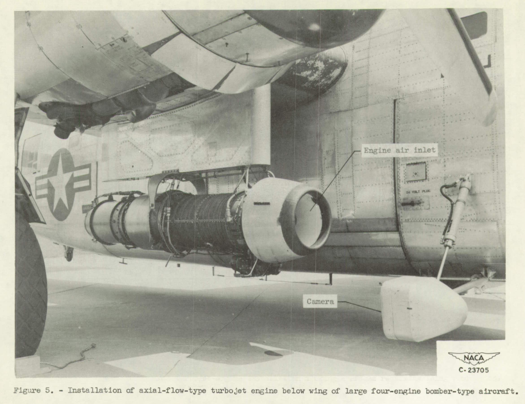
In the second flight investigation (references 2 to 4), an axial- flow-type engine of approximately 3000-pound rated sea-level static thrust was studied; The engine was mounted below the wing of a large four-engine bomber-type aircraft (fig. 5) and was instrumented to determine the effects of icing on engine performance. During the investigation, no compressor-inlet screen was used. Photographs of engine icing in flight were obtained with a camera so located that it could be swung into position to obtain pictures of the engine inlets. All investigations with this installation were conducted in natural flight icing conditions. The aircraft was also provided with equipment to evaluate the meteorological conditions prevailing throughout the flights.
Reference 2 is NACA-RM-E8C18, reference 3 is NACA-RM-E8F01a, and reference 4 is NACA-RM-E51C15 2.
Altitude wind tunnel. - An axial-flow-type engine similar to that used in the second flight investigation was mounted in a wing nacelle in the test section of the altitude wind tunnel (reference 5). This engine was fitted with an experimental hot-gas bleedback ice-protection system. The engine was instrumented to provide data for evaluating the performance of the engine and the hot-gas bleedback system in icing conditions. The investigations were conducted at various pressure altitudes up to 20,000 feet in simulated-icing conditions using spray nozzles.
Icing research tunnel. - Various ice-protection methods were evaluated in the 6- by 9-foot test section of the icing research tunnel with scaled research mockups of turbojet-engine-inlet components. Icing conditions with air temperatures as low as -30 F were obtained at air speeds up to 300 miles per hour and pressure altitudes below 3500 feet. Cloud droplet sizes and liquid-water contents in the tunnel were measured by the rotating-multicylinder method and were in the range of natural icing conditions. All models were instrumented to obtain pertinent pressure and temperature data.
ICING CHARACTERISTICS OF TURBOJET-ENGINE INSTALLATIONS
General ConsiderationsAll surfaces of a jet-engine installation that are exposed to direct impingement of water droplets may require icing protection (fig. 1). The engine and inlet components that are subject to icing are therefore inlet lips, accessory housing dome, islands and island fairings, compressor-inlet screen, inlet guide vanes, and compressor blading. In addition, other surfaces may require icing protection, such as duct-splitter plates, openings for boundary-layer bleedoff and accessory-cooling purposes, and curved inlet-duct walls subject to impingement caused by water separation from the inlet air stream.
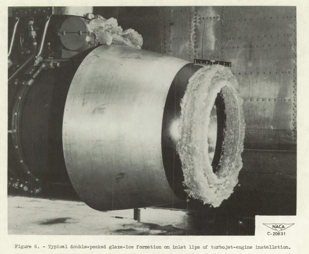
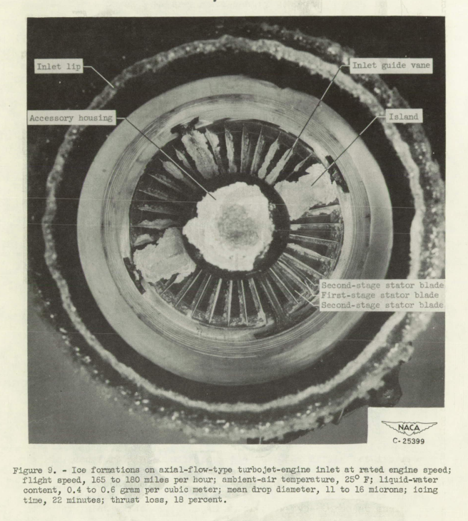
Meteorological factors. - The principal meteorological factors that contribute to icing are liquid-water content, air temperature, and droplet size. The rapidity with which ice builds up on the engine components and the time required to render the engine inoperative depend on the liquid-water content. The type of ice formation that occurs depends on the air temperature and the droplet size. Generally, the ice formations may be separated into two categories: (1) double-peaked glaze-ice formations in which the outer edges protrude laterally and forward into the air stream (fig. 6), and (2) wedge-shaped rime-ice formations, which build forward from the impingement area. Glaze icing is usually associated with air temperatures near freezing and relatively large droplet sizes. Rime icing is usually associated with low air temperatures and small droplet sizes.

The known meteorological factors conducive to aircraft icing are arranged in several classifications in reference 6. The range of possible meteorological factors in each classification is discussed and. specific values are recommended for the analysis of the various aircraft components.
Reference 6 is NACA-TN-1855.
Geometric and aerodynamic factors. - The paths of droplets are primarily influenced by the flow field about a body and the relative size of the droplets and the body. Because the flow field is determined by the shape of the body and the relative motion of the air stream, the shape greatly affects the extent of icing. Also, as the size of the body decreases relative to that of the droplet, the local icing rate is increased.
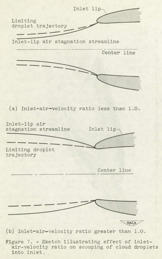
Icing of a turbojet engine is therefore affected by the aerodynamic characteristics of the engine installation. The number of water droplets entering the engine inlet is influenced by the inlet-velocity ratio (ratio of inlet-air velocity to the free-stream velocity), as illustrated in figure 7. The droplets contained within the limiting droplet trajectories enter the inlet whereas all droplets outside the limiting trajectories either impinge on the inlet body or pass around it. When the inlet-velocity ratio is less than 1.0, the area contained within the limiting droplet trajectories is greater than the area within the lip stagnation streamlines; hence the liquid-water content in the inlet is increased above that in the ambient air (fig. 7(a)). For an inlet-velocity ratio greater than 1.0, the area within the limiting trajectories is less than the area within the stagnation streamlines; hence the liquid-water content in the inlet is decreased below that in the ambient air (fig. 7(b)). Because of the scooping effect and the divergence of the streamlines when the inlet-velocity ratio is less than 1.0, icing on the inlet-duct walls may be expected.
The temperature-rise characteristics of each compressor stage and the adiabatic temperature change caused by flight speed influence the distance into the engine that ice formations occur. Obviously, as the temperature on the engine surfaces reaches a point above the freezing level, no ice will form.
Typical Icing of Components
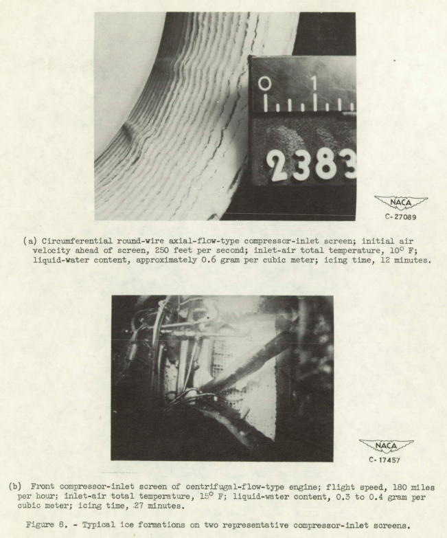
The icing tolerance of a turbojet engine is limited by the component having the smallest and most closely spaced elements. A compressor-inlet screen therefore constitutes the greatest icing hazard. In the absence of the compressor-inlet screen, the inlet guide vanes become the critical component. Examples of typical icing of turbojet-engine components are described in the following sections...
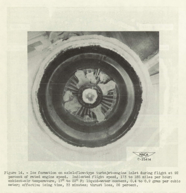
Effect of icing on axial-flow-type turbojet-engine performance. - The results of studies of icing effects on axial-flow-type engine performance are shown in figures 13 to 15. In natural flight icing conditions (fig. 13) with an axial-flow-type engine operating at 92 percent of rated engine speed, the engine thrust loss was 26 percent with an attendant 1600 F tail-pipe-temperature rise after an effective duration of approximately 30 minutes in icing (reference 4). During the time shown by the dotted portion of the curve, the icing was too intermittent and light for reliable measurements and the engine was stopped to conserve fuel. A photograph of the engine ice formations that caused the 26-percent loss in thrust is shown in figure 14. The compressor inlet is considerably blocked by large ice formations shed from the islands. In addition, ice can be plainly seen on the inlet guide vanes. The increase in thrust near the end of the run was caused by the breakup and subsequent passing through the engine of some of the large ice formations on the islands. Data presented in reference 4 indicate that the initial rate of thrust loss may be as high as 14 percent within 31 minutes of encountering an icing condition of moderate severity. After an initial rapid thrust loss, the rate at which the thrust is decreased may be reduced if the ice formations become dislodged or break off.
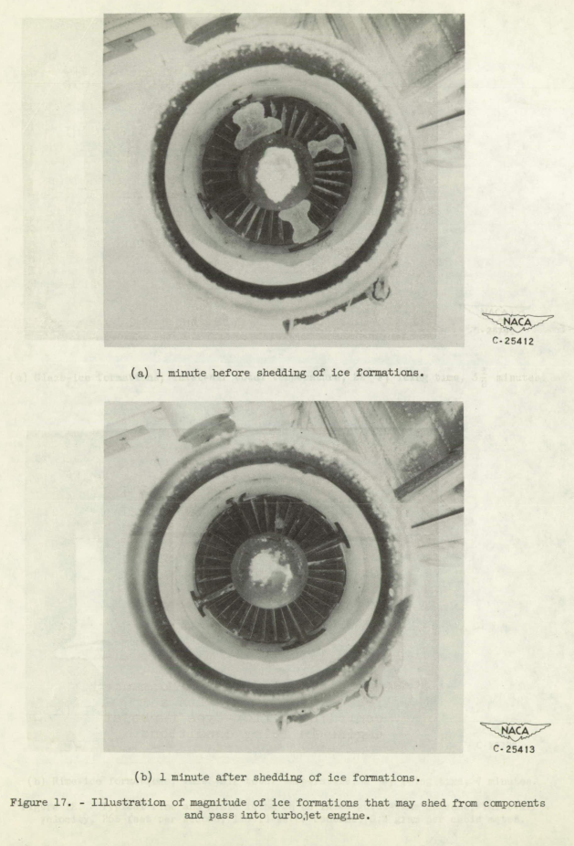
Damage caused by ice. - Shedding of large ice formations from components ahead of the compressor inlet when no compressor-inlet screen is used may cause engine blow-out and structural damage. An indication of the quantity of ice that may be shed from the inlet and the engine components and subsequently swallowed by the compressor is shown in figure 17 (reference 4). A photograph of the ice formations 1 minute before shedding occurred is shown in figure 17(a); figure 17(b) was taken 1 minute after the shedding of the ice formations. This sudden intake of ice caused a momentary drop of about 1000 rpm in engine speed. Inspection after shutdown showed no damage to the engine.
Ice shedding from inlet lips, accessory housing, and islands generally shatters into small pieces and passes harmlessly through the engine. Damage may occur if a large piece of ice lodges in the space between a rotor- and stator-blade stage or if a large piece strikes a rotor blade and deflects it into the guide vanes or stator blades. Wider inlet-guide-vane spacing permits passage of large ice pieces into the compressor and thereby increases the possibility of damage to the engine.
Freezing of water in the compressor daring outside parking or storage of an aircraft may result in damage if an attempt is made to start the engine before de-icing the compressor blading. No damage resulting from icing of centrifugal-flow-type turbojet engines has been reported to date.
Submerged-Inlet System
...
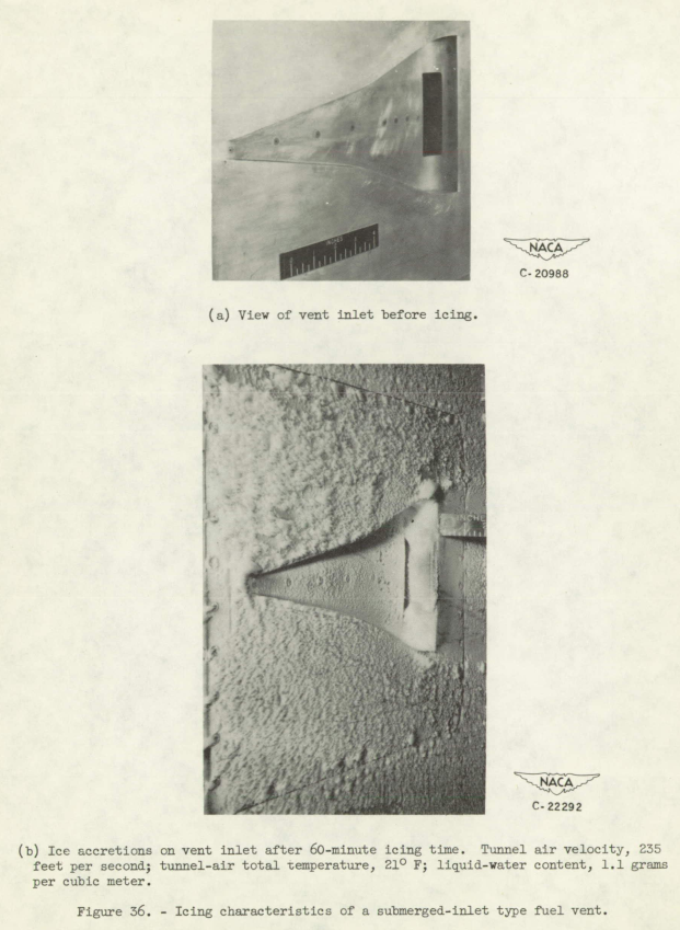
Other investigations of submerged-type inlets used in conjunction with fuel-cell vents are reported in reference 38. A typical vent installation using a submerged-type inlet mounted in the underside of a wing is shown in figure 36(a). Icing was observed on all surfaces of the inlet, namely, the ramp, the diverging sidewalls, and the inlet lip as shown in figure 36(b), and also on the wing surface ahead of the inlet. Although the air flow through the inlet (vent tubes) was quite low, the pressure losses associated with these ice formations (especially those on the surface ahead of the inlet) were found to be very high. Severe aerodynamic penalties can consequently be anticipated for engine installations requiring large quantities of air flow. Icing protection is therefore required for submerged-inlet components.
Conclusions
The need for icing protection of a turbojet engine results from the mass-flow and pressure losses associated with the icing of the various engine components. The compressor-inlet screen, in particular, constitutes a hazard that can cause engine failure in a matter of minutes. The inlet guide vanes of an axial-flow-type turbojet engine also represent a distinct hazard that could cause engine shutdown in a short period of time. The removal or retraction of the inlet screen is recommended to increase the engine icing tolerance and permit easier icing protection. In addition, an increase in the size and the spacing of the inlet guide vanes would be desirable. The rest of the engine components such as the inlet lips, the duct surfaces, the islands, and the accessory housing may require icing protection. The performance losses associated with icing of these components do not constitute an immediate danger to engine operation. The loss in performance caused by these ice formations may, however, result in a considerable decrease in the range and the speed of the aircraft. A centrifugal-flow-type turbojet engine is relatively unsusceptible to icing once the compressor screen has been removed.
Surface heating with hot gas involves the fabrication of ducts and passages beneath the surfaces to be heated. High-temperature materials and insulation add fabrication problems and small weight penalties. With either compressor-outlet or turbine-inlet bleedoff, heating of critical elements, such as guide vanes, can usually be accomplished with sufficient pressure and temperature remaining at the vane outlets to supply protection for some of the secondary elements, such as accessory housings and inlet ducts. During let-down conditions, the available gas pressure and temperature may be marginal for protection of the engine in severe icing conditions.
Difficulties encountered in the fabrication of electrical heating elements and the maintenance problems of an electrical heating system appear to be greater than for a hot-gas system.
The hot-gas-bleedback system (for heating inlet air) can be applied to current engines with minor modifications to the engine installation. The high temperatures and pressures required may be obtained by the bleedback of turbine-inlet gas or by compressor-outlet air with reheat.
A hot-gas-bleedback system that employs combustion gases will pollute the inlet air and affect the use of the compressor air for cabin pressurization purposes.
Icing protection may be obtained by any of the previously described systems. All the systems penalize the aircraft in icing conditions, either by performance losses caused by weight increases, or by thrust losses and increased specific fuel consumption; in nonicing conditions, however, the performance losses are negligible. Surface heating, by either electrical means or hot gas, appears to be the most acceptable in relation to performance losses in icing conditions. The choice of any particular system is dependent on the supply of heated gas and electrical power available and on the allowable performance and weight penalties.
Citations
NACA-RM-E51B12 is cited once, per scholar.google.com.
The single citations is:
- Potapczuk, Mark G.: “Aircraft Icing Research at NASA Glenn Research Center.” Journal of Aerospace Engineering 26 (2013): 260-276.
I find it hard to believe that a publication of this length and quality could languish virtually unnoticed for decades.
NACA-RM-E51B12 cites 38 publications, many of them prior NACA studies. Perhaps those studies were the ones that got used and cited, rather than NACA-RM-E51B12. However, NACA-RM-E51B12 includes original work, and is not just a compilation of past efforts.
NACA-RM-E51B12 cites NACA-RM-E50C15 ("reference 4), which provides an explanation of how they were able to get photos of the engine ice during the flight tests:

Figure 3 of NACA-RM-E50C15.
Related
This is part of the Engine Inlet Icing Thread.
Notes
-
von Glahn, Uwe H., Callaghan, Edmund E., and Gray, Vernon H.: NACA Investigations of Icing-Protection Systems for Turbojet-Engine Installations. NACA-RM-E51B12, 1951. ntrs.nasa.gov ↩
-
Acker, Loren W., and Kleinknecht, Kenneth S.: Effects of Inlet Icing on Performance of Axial-Flow Turbojet Engine in Natural Icing Conditions. NACA-RM-E50C15, 1950. ntrs.nasa.gov ↩