"The icing of the unprotected installation presents a serious operational problem"
"Wind-Tunnel Investigation of Icing of an Engine Cooling-Fan Installation" 1
Abstract
An investigation was made of the icing characteristics and means of ice protection of a typIcal radial-engine cooling-fan installation, The investigation was made at various icing and performance conditions in the icing research tunnel of the NACA Cleveland laboratory.
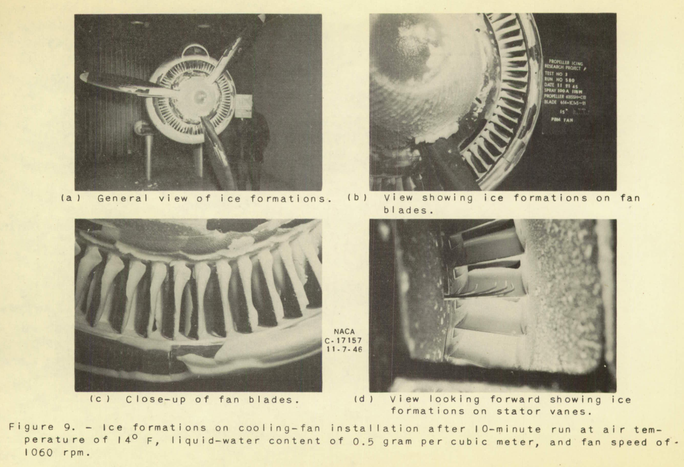
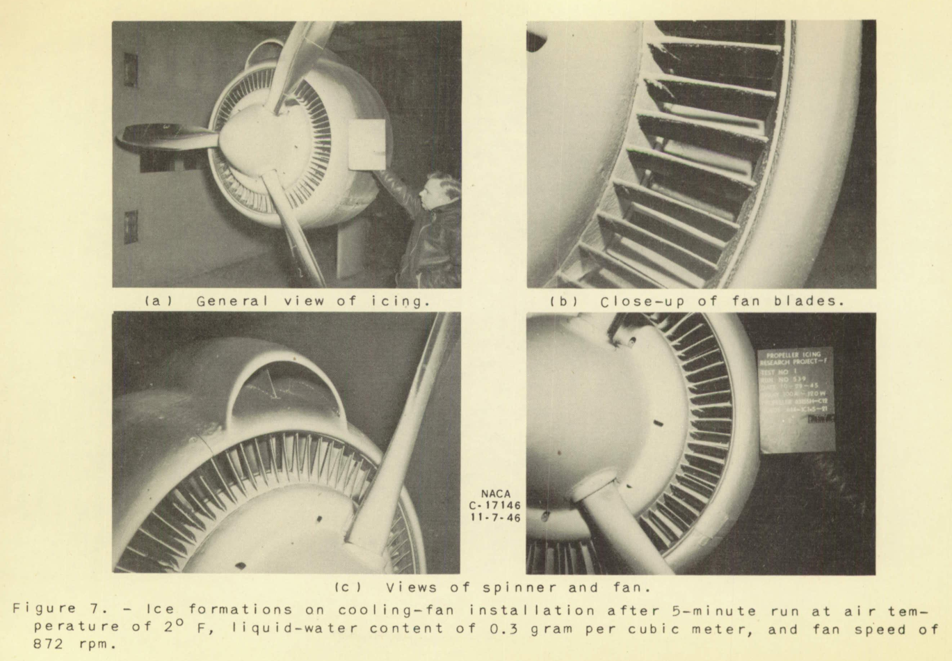
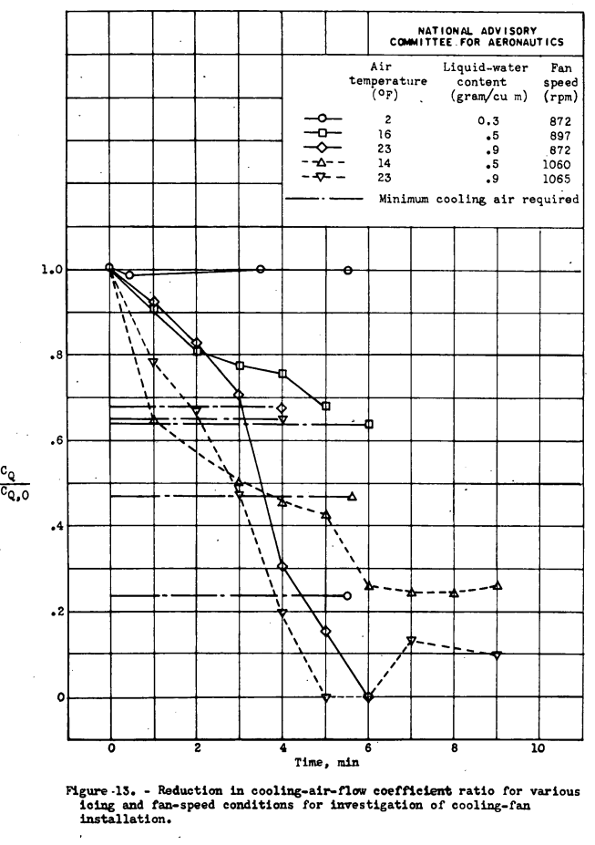
The icing of the unprotected cooling-fan installation was found to present a serious operational problem. Reduction in air flow below the minimum value required for engine cooling occurred within 2 minutes and complete stoppage of the cooling-air flow through the fan assembly occurred in as little as 5 minutes under normal icing conditions.
Steam de-icing was found to be effective for the cowling lip and inlet duct. Alcohol de-icing of the fan blades and stator vanes was found to be unsatisfactory. Electrical heat de-icing of the fan blades was found to be effective but de-icing of the stator vanes was not completely effective at the power densities investigated.
Discussion
This publication is fairly long (40 pages), so only selected sections and figures are reproduced here to illustrate the results.
APPARATUS
The investigation was conducted in the diffuser section of the icing research tunnel. The cooling-fan assembly was mounted on the modified nose section of an airplane fuselage installed in the tunnel. The installation consisted of a typical propeller-speed engine cooling fan, a stator-vane and diffuser assembly, a baffle plate located in a constant-area annular duct downstream of the fan to simulate the pressure drop across the engine, a standard radial-engine cowling, a three-blade propeller and spinner, and necessary instrumentation. (See fig. 1.)
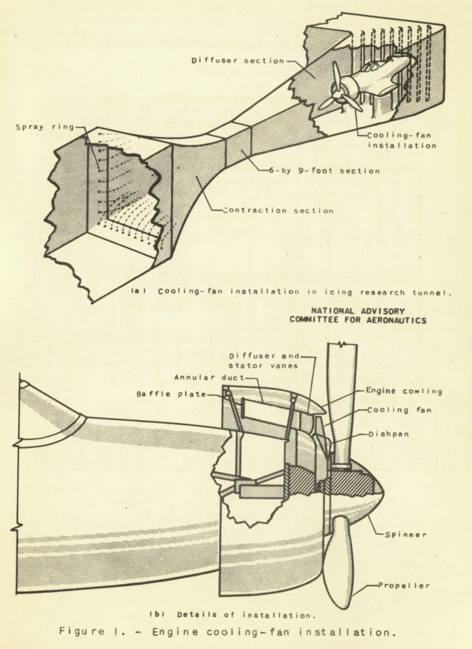
Cooling fan. - The cooling-fan assembly was designed to be mounted at the front face of a radial engine and enclosed by the engine cowling with the fan rotor attached to the rear of the propeller hub and the stator-vane assembly attached to the reduction-gear housing. The front fairing of the fan disk was of the "dish-pan" type with a large forward bulge at the outer diameter of the dishpan. The fan bad 72 cambered, sheet-metal blades with a tip diameter of 43 inches and a tip clearance of three-sixteenths inch. As part of the cooling-fan assembly, 49 cambered. sheet-metal stator vanes were located behind the fan to remove the rotational component of the flow. A clearance of seven-eighths inch existed between the fan blades and stator vanes. (See fig. 1.)
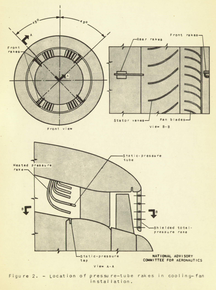
Instrumentation. - Total pressure in front of the fan and total and static pressure behind the stator vanes were measured by pressure-tube rakes (fig. 2), Four equally spaced rakes of shielded total-pressure tubes were located at the lip of the engine cowling between the fan and propeller. These rakes were unheated. because of the extreme difficulty in heating small shielded total-pressure tubes and hence were used only on nonicing pressure-distribution studies. Electrically heated rakes consisting of four total-pressure tubes and one static-pressure tube were installed behind the stator vanes at four equally spaced positions corresponding to the positions of the front rakes. In addition, static pressures were measured on the inner wall of the diffuser in the plane of the rear rakes. All the pressures wore indicated on a multiple-tube manometer and were photographically recorded.
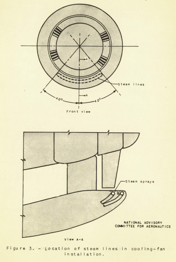
Steam-heat Installation. - In order to investigate the elimination of ice on the engine-cowling lip and the consequent scraping of the fan-blade tips, one steam line with jets 0.10-inch in diameter and spaced 1/2 inch apart was placed inside the cowling lip and another was located outside the inlet duct 2 inches behind the first line (fig. 3). These lines were of 3/8-inch copper tubing and extended approximately 40° on each side of the center line in the lower half of the cowling. Steam heating was confined to the lower quarter of the cowling because of time limitations and also to provide an unheated area for comparison.
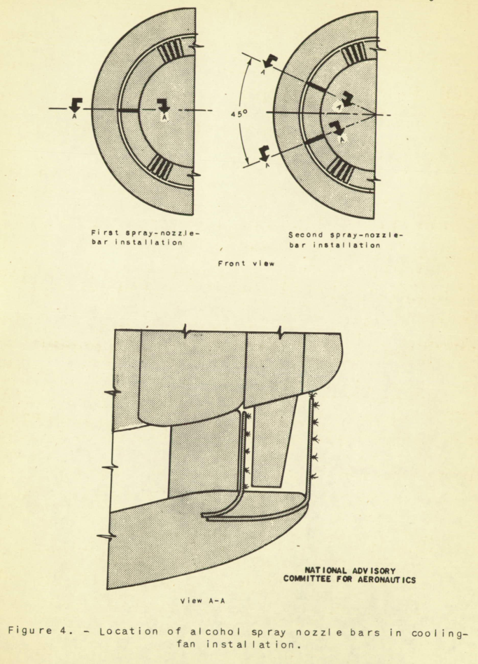
Alcohol de-icing installation, - In the investigation of the use of isopropyl alcohol for de-icing, spray nozzle bars were mounted radially in front of the fan blades and also between the fan blades and the stator vanes (fig. 4), The spray nozzle bars, consisting of tubes having six small jets each 0.070 inch. in diameter, were mounted to spray the alcohol forward in an attempt to obtain a good spray dispersion and at the same time to keep the spray tubes de-iced. For the first installation a single nozzle bar was mounted horizontally in front of the fan blades and one in a corresponding position was mounted at the leading edge of the stator vanes. For the second installation two spray nozzle bars located approximately 45° apart were similarly mounted in front of the fan blades and two spray nozzle bars were also mounted at the leading edge of the stator vanes, This second configuration was used to obtain a greater coverage of alcohol on the stator vanes and to accommodate greater flows, A variable-control alcohol pump provided flow rates up to 2.3 pounds per minute.
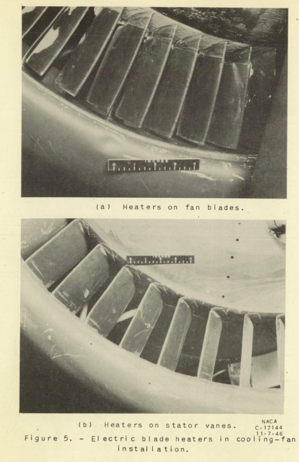
Electrical-heat do-icing installation. - The use of electric heaters for de-icing was confined to the fan blades and stator vanes, as shown in figure 5. Because of the large number of blades and the anticipated large power requirements, only a few of the blades were so heated. The blade heaters were similar to propeller-blade de-icing heaters and consisted cf parallel chordwise electrical resistance wires enclosed, between two layers of neoprene cemented to cover the entire chord of both blade faces. Because the heaters were rectangular, they did not fully protect the inner ends of the fan-blade leading edges. Heaters were applied to twelve of the 72 fan blades, arranged in two groups of six consecutive blades diametrically opposite and to six consecutive stator vanes. The heated area on each fan blade uas 21.3 square inches with a resistance of 12 ohms per blade; the heated area cn a stator vane was 39 square inches with a resistance of 16 ohms per vane. The power density of the heaters was uniform. The twelve heaters on the fan blades were connected in series in one circuit and the six heaters on the stator vanes were also series-connected in a second circuit. Power to the blade heaters was metered through a variable resistance and transmitted to the fan through a slip ring mounted on the propeller hub behind the fan. An electronic cycle timer permitted the cyclical application of power to the blade heaters.
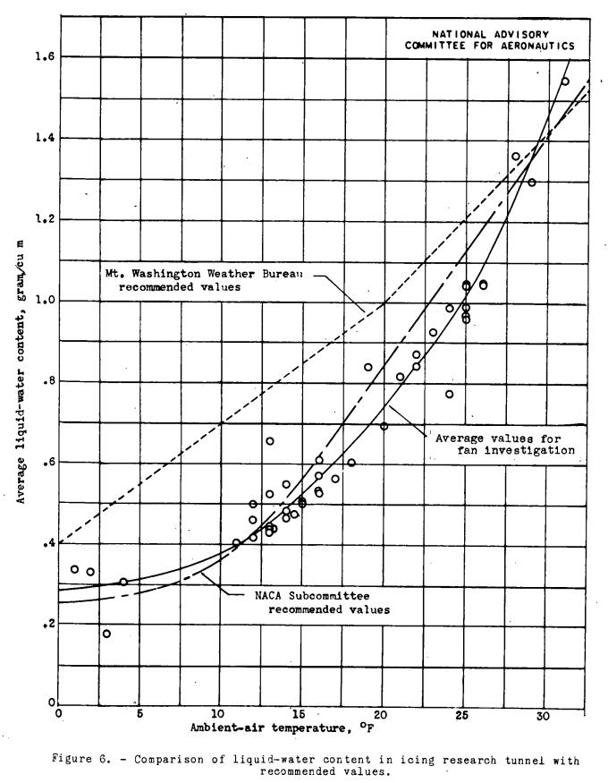
Calibration of tunnel-icing conditions. - The icing conditions were defined by the ambient-air temperature and liquid-water content of the air. Figure 6 presents the variation of liquid-water content with air temperature at the face of the cooling fan as determined by a survey conducted in the diffuser section of the icing research tunnel and a comparison of these conditions with the values recommended by the NACA Subcommittee on De-Icing Problems and by the Mt. Washington Weather Bureau meeting on June 19, 1945. The subcommittee values are one-half of the recommended maximum values and are for average or typical icing. Vertical cylinders rotating about their axes were installed in the diffuser section and, from measurements of the local velocity and the ice accumulation per unit time on these cylinders, the average liquid-water content in grams per cubic meter for each condition of tunnel air velocity, ambient-air temperature, and spray-water input pressure was computed by the method of Langmuir of the General Electric Company. Droplet size was also measured but no consistent correlation with air temperature was obtained. An average droplet size of 55 microns was obtained in the icing research tunnel for the range of air temperature of 0° to 32° F as compared with the recommended averages of 10 and 30 microns, respectively, at these temperatures. This variation in droplet size was not considered important, however, because the collection efficiency of small objects such as th.e thin fan blades and stator vanes is known to be very close to 100 percent, Although the liquid-water concentrations are slightly less than the recommended values for most of the temperature range, the experimental values are nevertheless representative of moderate-to-light icing conditions encountered in the United States. This survey was made approximately 3 months before the cooling-fan investigation. Although time limitations prevented any extensive checks of the liquid-water content and distribution, visual observations of the spray cloud and icing of the installation and tunnel, together with readings of spray-water input pressures, indicated that the icing conditions were fairly constant and in fairly close agreement with the indicated values for the cooling-fan investigation. A velocity survey made after this investigation indicated, however, that the icing of the contraction section of the tunnel resulted in an increase in the thickness of the tunnel boundary layer with a corresponding increase in the velocity at the center of the tunnel. In addition to the change in velocity distribution, this increase in boundary layer also caused some changes in liquid-water content and distribution.
RESULTS AND DISCUSSION
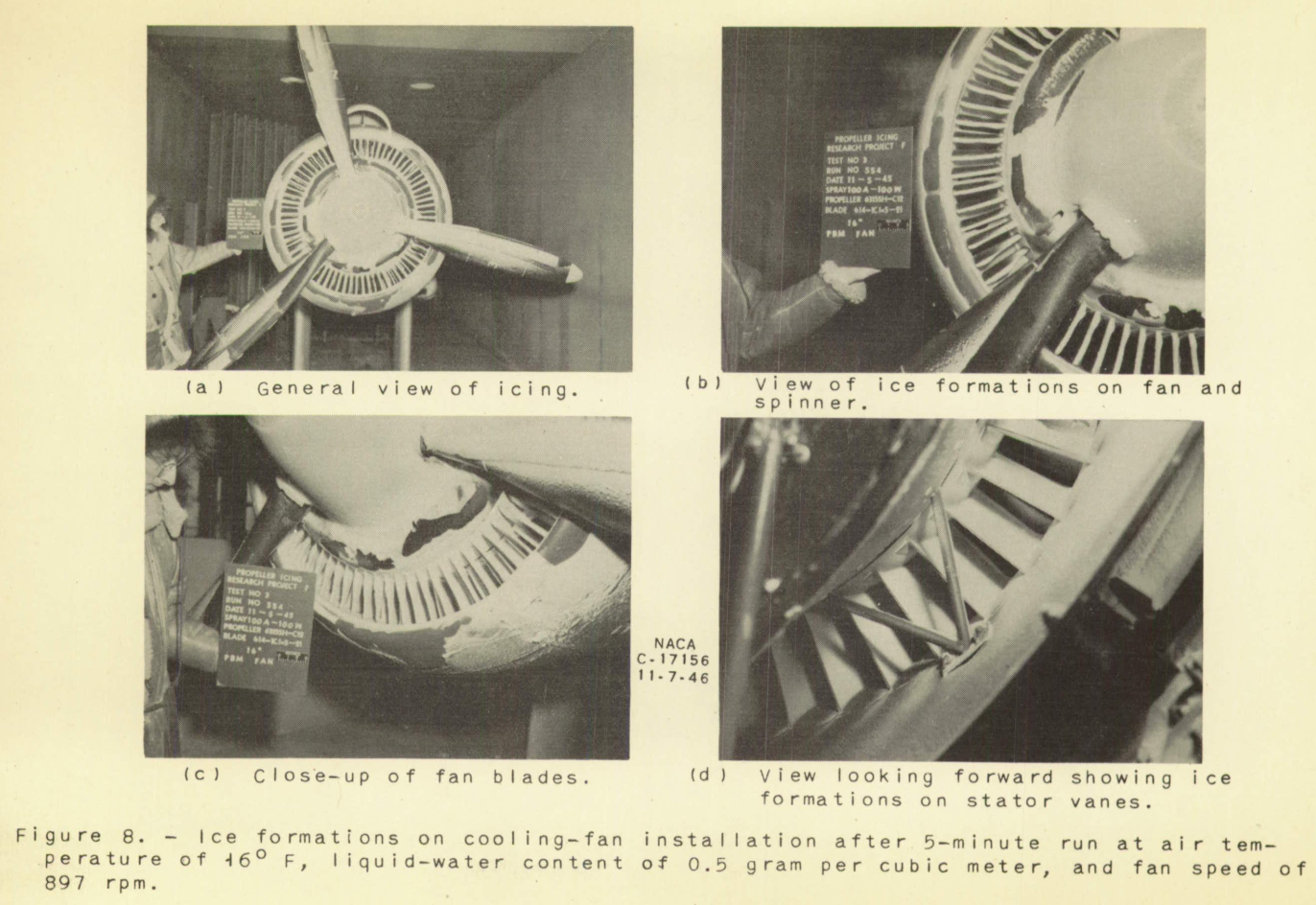
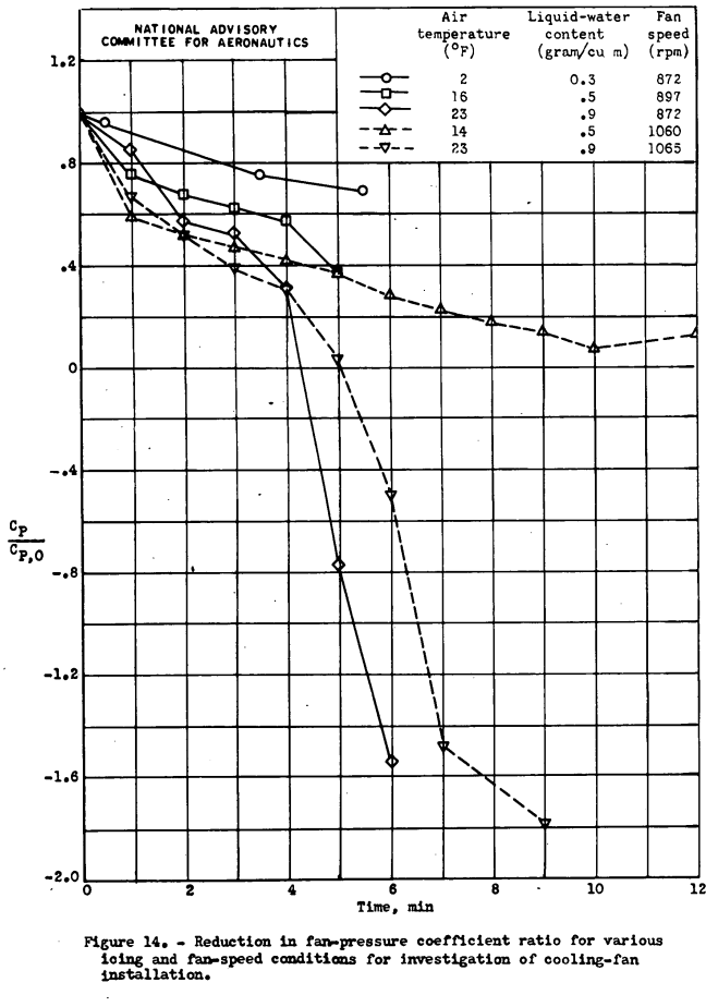
Icing - Photographs ebowing typical icing of the fan assembly at the conditions tested are shown in figures 7 to 12, The effects of icing on fan performance re shown in figures 13 and 14 where the ratios of the air flow and fan pressure of the iced fan to that of the fan before icing CQ/CQ0 and CP/CP0, respectively, are plotted against icing time. Although insufficient data were available to compare the effects of icing at all icing and performance conditions, the results shown in figures 13 and 14 are complete enough to define the effects of icing on fan performance throughout the normal range of icing and performance conditions, The minimum air flow required for adequate engine cooling is indicated in figure 13 as computed. from data supplied by the engine manufacturer.

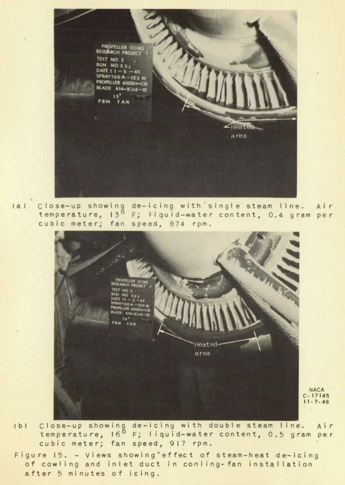
Steam-heat de-icing, - The results of a brief qualitative investigation of the use of steam for de-icing the cowling lip and inlet duct are shown in figure 15. Figure 15(a) shows the results of de-icing with a single steam line placed outside the inlet duct at the tip of the fan blades, The heated area started to throw off ice 50 seconds after the steam was turned on and all the ice was removed within 2 minutes with the heated area remaining clear thereafter. In a delayed de-icing run with the same configuration, steam was turned on after 5 minutes of icing and the ice in the | heated area was thrown off within 30 seconds. With the double steam line installed (fig.15(b)), a slightly greater area including thé lip of the engine cowling was de-iced in the same time. From these results, it appears that the de-icing of these areas by means of hot gases is entirely feasible.
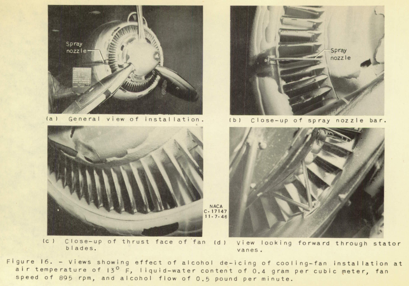
Alcohol de-icing, - The results of the use of alcohol sprays are shown in figures 16 to 20. At an alcohol flow of 0.5 pound per minute and with the initial spray configurations, fairly good de-icing of the fan blades was obtained at an air temperature of 13° F end liquid-water content of 0.4 gram per cubic meter (fig. 16). A fairly heavy accumulation of slush was retained, however, on several stator vanes that were concave upward.
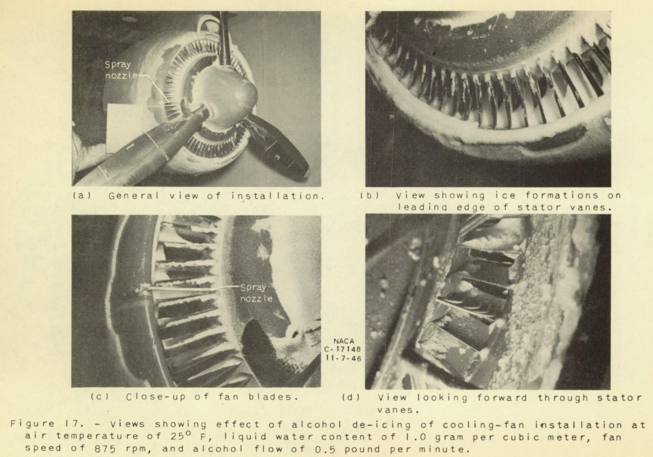
At a higher air temperature and water content and with the same alcohol flow (fig. 17), the fan blades were only partly de-iced and all the stator vanes were partly blocked by similar deposits of slush.
When the alcohol flow was increased to 1.2 pounds per minute at approximately the same icing and speed conditions and with the second spray configuration, no improvement in de-icing was apparent (fig. 18). Although the convex face of the fan blades was almost completely clear of ice, heavy deposits of slush were as much as three-fourths inch thick at the concave-face trailing edge, The stator vanes again had large formations of wet ice and were approximately 50-percent blocked. At a medium icing condition (air temperature, 14° F and liquid-water content, 0.5 gram/cu m) and an alcohol flow of 1.5 pounds per minute, the fan blades were almost fully de-iced. (See fig. 19.)
Medium formations of wet ice were found on the stator vanes immediately behind the spray tubes and only 2 thin coating of ice was found on the rest of the stator blades, When the alcohol flow was increased to 2.3 pounds per minute, the fan blades were again almost completely de-iced (fig. 20). Large deposits accumulated, however, on all the stator vanes. As shown by the photographs of all the alcohol de-icing (figs, 16.to 20), the alcohol-diluted ice thrown off the fan blades impinged on the stator vanes where it remained and refroze. For all conditions, configurations, and flows investigated, the use of alcohol as a de-icing agent proved ineffective because of the marginal de-icing of the fan blades and the large ice deposits obtained on the stator vanes. It is estimated that no practical amount of alcohol would satisfactorily preserve fan performance under all icing conditions.
Electrical heat de-icing. - - Photographs showing the results. of the use of electric blade heaters are presented in figures 21.to 25, As only a few of the fan blades and stator vanes were heated, no fan-performance data were obtained. With an air temperature of 15° F, liquid-water content of 0.5 gram per cubic meter, fan speed of 954 rpm, and a power density of 5 watts per square inch, fairly complete de-icing of the heated fan blades resulted (See fig, 21.)
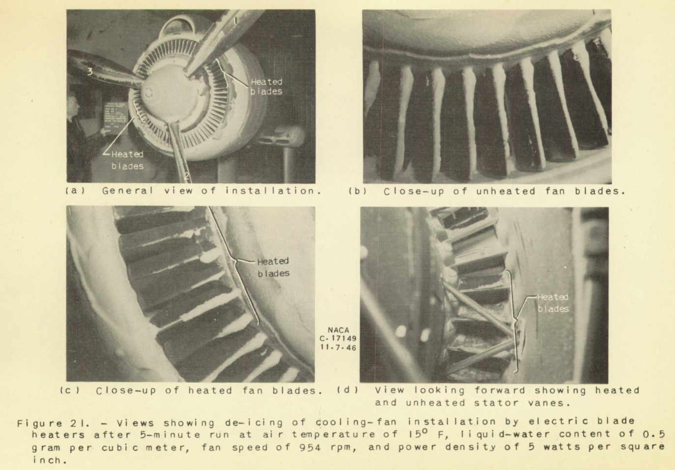
The small amount of ice at the root of the leading edge was caused by ice bridging over from an unheated part of the blade. It should be noted that the group of heated fan blades behind propeller blade 1 were partly shielded from icing by the blade shank. The de-icing of the stator vanes was only marginal with rough ice building up near the trailing edge. When the power density was increased to 6 watts per square inch (fig. 22), some improvement in the de-icing of the stator vanes resulted but rough ice still collected at the trailing edge. At a higher temperature and liquid-water content (fig. 23) complete de-icing of the heated fan blades was obtained after 5 minutes of icing. The de-icing of the stator vanes was again marginal. The effects of electrical heating at two icing conditions, each of 10-minute duration, are shown in figures 24 and 25, Both experiments were made at power densities of 6 watts per square inch with the fan blades almost completely de-iced. At the lower temperature, the de-icing of the stator vanes was marginal and at the higher temperature and liquid-water content, the de-icing of the stator vanes was completely ineffective.
Conclusions
The results of an icing investigation of a conventional radial-engine cooling-fan installation in the icing research tunnel indicate that:
1. The icing of the unprotected installation presents a serious operational problem. Reduction in air flow below the minimum value required for adequate engine cooling occurred within 2 minutes and complete stoppage of the cooling-air flow through the fan assembly occurred within 5 minutes under normal icing conditions.
2. Steam de-icing of the cowling lip and inlet duct showed the feasibility of hot gas de-icing for this portion of the assembly.
3. Alcohol de-icing of the fan proved to be ineffective and, in some cases, increased the icing problem by causing large formations on the stator vanes.
4. Electrical heat do-icing was the most promising method of de-icing the blades. The fan blades required a minimum power density of 6 watts per square inch but for the stator vanes this power density proved insufficient.
Citations
This publication is not cited in the literature, per scholar.google.com.
Related
See NACA-RM-E51B12 "NACA Investigations of Icing-Protection Systems for Turbojet-Engine Installations" for a description of a hot gas recirculation anti-ice system for jet engines, similar to the steam heating discussed here.
This is part of the Engine Inlet Icing Thread.
Notes
-
Lewis, James P.: Wind-Tunnel Investigation of Icing of an Engine Cooling-Fan Installation. NACA-TN-1246, 1947. ntrs.nasa.gov ↩