"Ice formations ... may have the following effects, which when combined may become serious enough to necessitate a shutdown of the engine: reduced engine thrust, increased,fuel consumption, and increased tail-pipe temperature."
"Icing Characteristics and Anti-Icing Heat Requirements for Hollow and Internally Modified Gas-Heated Inlet Guide Vanes" 1
Abstract
A two-dimensional inlet-guide-vane cascade was investigated to determine the effects of ice formations on the pressure losses across the guide vanes and to evaluate the heated gas flow and temperature required to prevent icing at various conditions. A gas flow of approximately 0.4 percent of the inlet-air flow was necessary for anti-icing a hollow guide-vane stage at an inlet-gas temperature of 500° F under the following icing conditions: air velocity, 280 miles per hour; water content, 0.9 gram per cubic meter; and inlet-air static temperature, 0° F. Also presented are the anti-icing gas flows required with modifications of the hollow internal gas passage, which show heat-input savings greater than 50 percent.
Discussion
INTRODUCTION
Ice formations on turbojet-engine inlet guide vanes cause a pressure reduction in the air entering the first rotor stage. This pressure reduction may have the following effects, which when combined may become serious enough to necessitate shutdown of the engine: reduced engine thrust, increased,fuel consumption, and increased tail-pipe temperature.
The investigation reported' herein was conducted at the NACA Lewis laboratory to determine the magnitude of pressure losses caused by various ice formations on an unheated inlet guide-vane cascade and the heat required to prevent ice formations. A convenient source of heat for hollow inlet guide vanes is hot air bled from the compressor outlet or hot gas bled from the combustion-chamber outlet. In this investigation, heated air was utilized to determine the flow rates and temperatures required to prevent icing. Two guide vanes with internal modifications were investigated and compared with a hollow vane to evaluate the reductions in heating rates possible with internal-flow-passage alterations.
The research installation comprised a fixed two-dimensional cascade of five vanes that spanned a short rectangular duct mounted in the 6- by 9-foot icing research tunnel. The vane chord was 2-3/8 inches, the gap between vanes was 3-1/8 inches, and the span was 5.9 inches. Vanes of smaller chord and gap size may be more effective aerodynamically, but will become more quickly blocked with ice under icing conditions. In addition, smaller vanes are more difficult to equip with internal instrumentation.
The range of conditions investigated was as follows:
Inlet-air velocity, mph ............178 to 304
Inlet-air total temperature, OF .....-23 to 23
Water content, gram/cu m ...........0.3 to 1.0
Pressure altitude, ft...............below 3500
Current turbojet engines utilize inlet-air velocities greater than those obtainable in the icing research tunnel; from the velocities investigated, however, the anti-icing requirements at higher air-velocities may be estimated.
Heat requirements for icing protection of inlet guide vanes have also been obtained in a concurrent investigation (reference 1) utilizing electrical resistance elements imbedded in a solid metal guide vane.
APPARATUS AND MODELS
The installation in the icing research tunnel of the five-guide-vane cascade and the surrounding duct is shown in figure 1. The four tubes upstream of the vanes and the horizontal and vertical rakes downstream of the vanes were used to measure the pressure loss across the vanes. Additional wall static taps were provided for the pressure study. The horizontal rake was gas-heated and all total-pressure tubes were electrically heated. The four duct walls, the inlet lips, and the center-support fairing were anti-iced by hot gas independent of the vane heating system. The guide vanes were thus the only surfaces to collect ice during heat-off operation of the vanes.
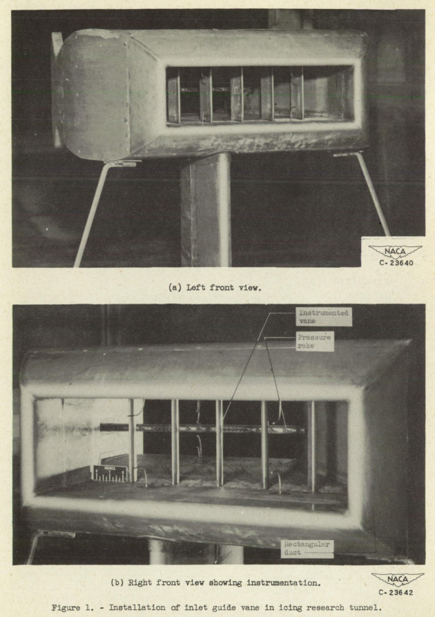
The heat supply for the five guide vanes consisted of compressed. air heated in a heat exchanger by combustion products of a jet burner. Cold air and valving for mixing hot and cold gas as desired, as well as a regulator for controlling the flow, were provided. The heated gas was distributed through a manifold to the five vanes; it then flowed upward through the vanes into an outlet passage that exhausted into the tunnel air. The gas flow for the center vane was determined by a calibrated metering box in the line. The gas temperature was measured by thermocouples in the inlet manifold, the center-vane inlet and midpoint, and by a five-point thermocouple rake at the outlet. The center vane was insulated at both ends from the duct walls and manifolds.
CONDITIONS AND PROCEDURE
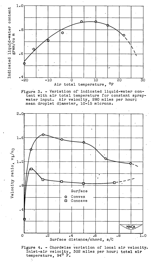
A calibration of the water content of the tunnel air was made just upstream of the vane duct for the range of air temperatures. The variation in liquid-water content is shown in figure 3 as measured by standard rotating-cylinder technique when the water flow through the nozzles was-held constant and the air temperature varied. The air was saturated at all temperatures prior to sprays and the velocity was constant; therefore, the liquid-water content should also have been approximately constant. The reduction in measured liquid-water content at temperatures approaching the freezing point could be due to water blow-off from the cylinders occurring because of slow freezing rates, and the reduction at lower temperatures could be due to freeze-out of the spry droplets before reaching the models. The calibration shown in figure 3 was used in conjunction with the spray water-flow readings to determine the effective water content of the air passing through the guide vanes. The mean droplet diameter was in the range of 10 to 15 microns.
Icing Characteristics and Pressure Losses
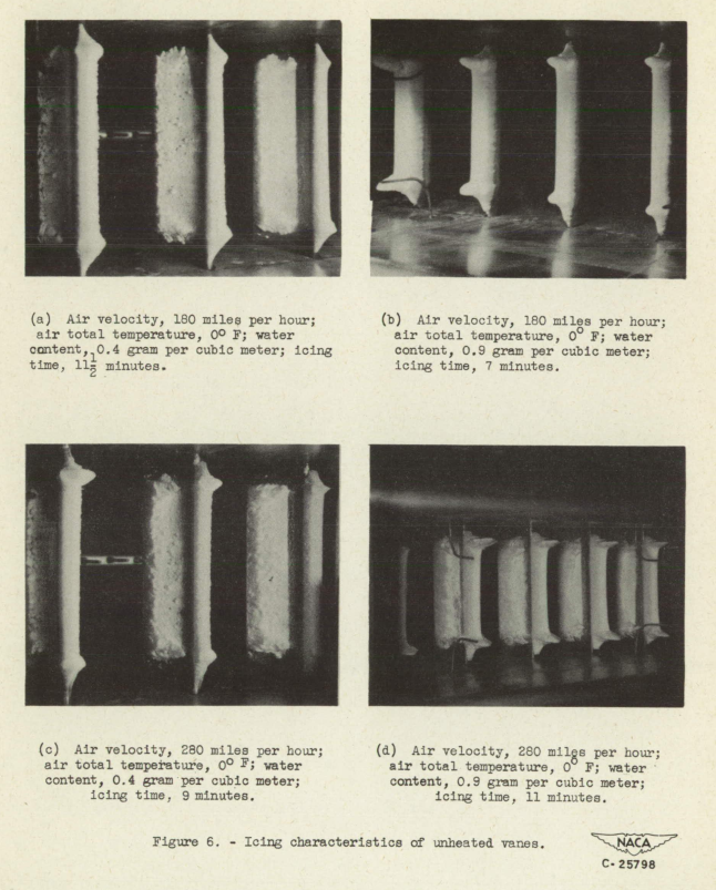
Unheated vanes. - The nature of the ice formations that accumulate on unheated guide vanes can be observed in figure 6 for eight icing conditions and various icing times. A distinct difference is apparent between the formations at a total air temperature of 0° F and those at 22° F. Because the ice formations built out laterally at the high air temperature, a wide and nodular front was presented to the air stream; whereas at 0° F, where the ice built directly forward into the air stream, the leading edge maintained a regular, wedge-shaped cross section. The variables water content, air velocity, and icing time contributed principally to the amount of ice accretion.
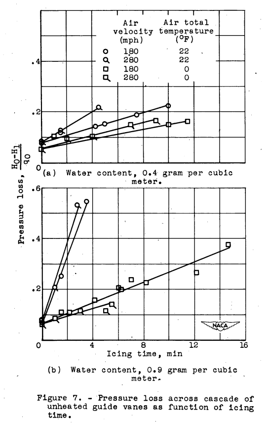
The pressure losses associated with these ice formations are presented in figure 7, where the pressure loss is plotted as a function of time under icing conditions. The losses increased rapidly at the 22° F air temperature, especially at a water content of 0.9 gram per cubic meter; a maximum of 54 percent was reached in an icing time of 3 minutes. The pressure loss showed a minor variation with air velocity, a marked variation with water content, and an approximately linear variation with icing time. From figure 7 and the photographs in figure 6, the losses at the higher water content were serious even at an air temperature of 0° F; greater and more rapid losses may be anticipated for cascades with gap and chord sizes smaller than those reported herein.
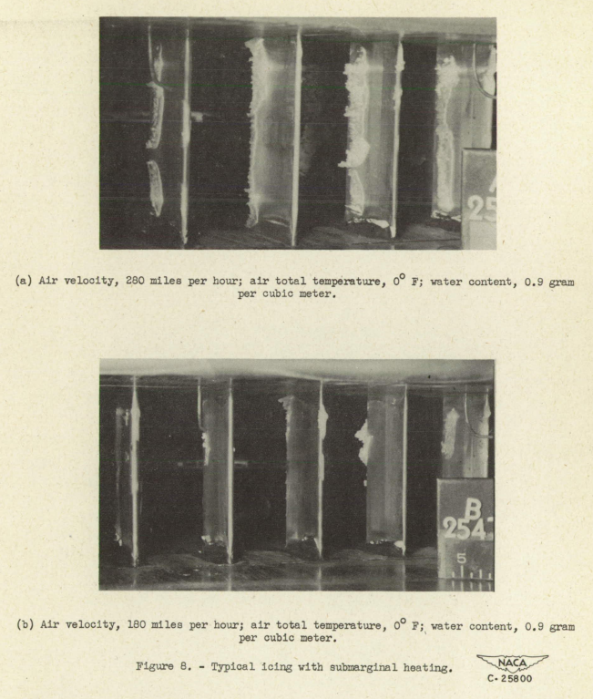
Heated vanes. - Without ice on the vanes, the pressure losses ranged from 4 to 8 percent across the cascade. The losses with marginal and submarginal anti-icing were briefly investigated. With insufficient heating, the vanes iced as shown in figure 8. The mid-chord regions of the vanes were ice-free, the leading edges had slight deposits, and the trailing portions had considerably more ice. When the heating was submarginal, the pressure loss was increased approximately 4 percent more by the ice shown in figure 8(a) than for the uniced condition. At conditions nearer the marginal heating level, the residual ice deposits were small and presented the spotty appearance shown in figure 8(b). Because of the upward gas flow through the vanes and the consequent spanwise temperature drop, the gas temperature was lowest at the top of the vane; heating insufficient to prevent ice on the top half of the vanes resulted.

...
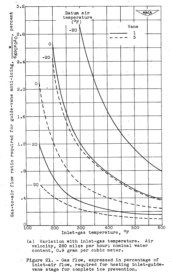
The gas flow required for guide-vane ice prevention may be expressed in percent of air flow across the vanes. Such a relation is presented in figure 21 as a 1 function of inlet-gas temperature and inlet-air velocity for vanes 1 and 3. At an air velocity of 280 miles per hour (fig. 21(a)), the static air temperature was approximately 9°F lower than the corresponding datum air temperatures. At an inlet-gas temperature of 500° F, the calculated gas flow required for prevention of icing on a guide-vane stage of the hollow-vane type was approximately 0.5 percent of the inlet-air flow at a datum air temperature of 0° F. At an inlet-air, static temperature of 0° F, the requirement was approximately 0.4 percent of the air flow. The gas-flow requirement at this condition for a stage of the vane 3 type was approximately 0.2 percent of the air flow.
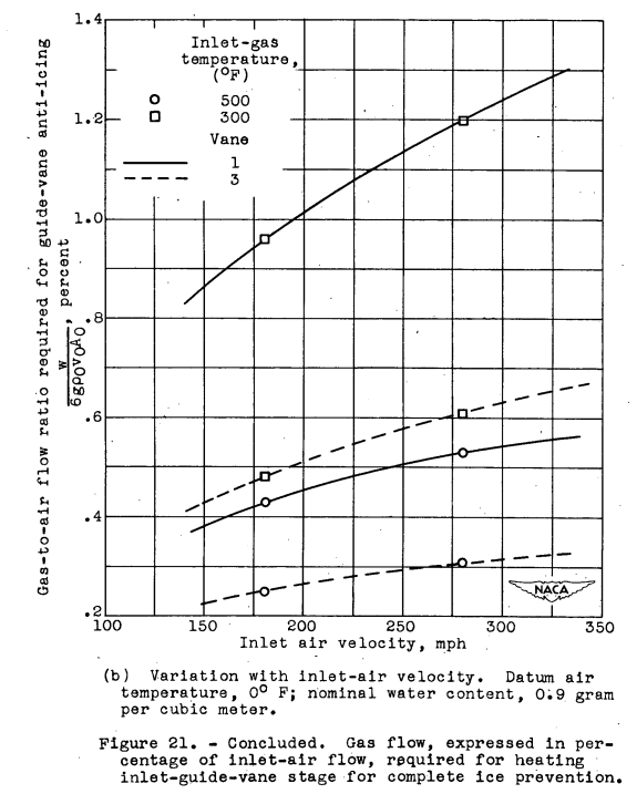
The gas-to-air flow ratio required for anti-icing a guide-vane stage is given in figure 21(b) as a function of the inlet-air velocity. The relation is shown for vanes 1 and 3 with inlet-gas temperatures assumed constant at 300° and 500° F for a datum air temperature of 00 F and water content of 0.9 gram per cubic meter. An increase with air velocity is shown in the gas-to-air flow percent requirement; this increase resulted from the assumed constant gas-inlet temperature and variable gas flow. By use of figure 21, guide-vane anti-icing heat requirements at inlet-air velocities different from those investigated may be estimated.
Pressure altitudes above 3500 feet were not investigated; however, previous investigations have indicated that anti-icing heat requirements do not vary greatly with altitude alone.
The values in Figure 21a of heating flow equal to 2 to 3 % of the flow through the vanes (equal to the fraction of core flow to be extracted for a turbojet configuration) for lower heated air temperatures are rather high. A designer would have to balance that against the pressure loss through the vanes if there is no ice protection as in Figure 7 (however, the values are not in the same units, and the relative importance between them depends on details of the engine cycle).
The value of approximately 0.3 % in Figure 21b for the optimized Vane 3 design with 500° F heated air is more tenable, but still non-trivial.
Many more current, turbofan designs do not include heating of the inlet guide vanes for ice protection. Often, the only components heated are air data probes used in the engine controls.
Conclusions
In an investigation of the icing characteristics and anti-icing heat requirements for a two-dimensional cascade of gas-heated inlet guide vanes having hollow and modified internal passages, the following results were obtained:
Losses in ram pressure up to 54 percent after 3 minutes of icing may result when ice forms on unheated guide vanes. The losses are greater at air temperatures near 22° F than at 0° F because of the characteristic shapes of ice deposits at the two temperatures.
At a particular spanwise station, the heat flow in the internal gas stream required to prevent icing on an entirely hollow guide vane was approximately 9200 Btu per hour at a gas temperature of 273° F when the gas flow per unit passage area was at the rate of 6x10^4 pounds per hour per square foot and when the following serious icing condition was imposed: datum air temperature, 0° F; air velocity, 280 miles per hour; water content, 0.9 gram per cubic meter. For the same condition, the heating requirements were reduced approximately 40 and 50 percent, respectively, when the vanes were modified internally by (a) a spanwise sheet-metal fin attached at the vane internal leading and trailing edges and supporting a center insert, and (b) a spanwise insulating insert attached near midchord to the convex surface. The heating required to completely prevent icing on a guide-vane station was approximately 40 percent more than that required to maintain only an ice-free leading edge.
For ice prevention over the complete vane span and chord, the hollow vane required an internal heat flow at the vane inlet of 11,900 and 7600 Btu per hour at inlet-gas temperatures of 300° and 600° F, respectively, in the serious icing condition previously mentioned. The vane modified with an insulating insert required from 39 to 67 percent as much heat input as the hollow vane, depending on air and gas temperature. When gas at an inlet temperature of 500° F was used, the hollow vane and the vane with an insert required gas flows only 0.4 and 0.2 percent, respectively, of the inlet-air flow for complete ice prevention at an air velocity of 280 miles per hour, a water content of 0.9 gram per cubic meter, and an inlet-air static temperature of 0° F.
The vane with fin and insert required nearly as much heat input as the hollow vane because of a high heat-dissipation rate over most of the chordal extent of the vane except at the trailing edge where the internal-gas velocity and temperature were comparatively low. The vane with only an insert had the greatest heating rate at the trailing edge and the greatest efficiency in chordwise heat transfer.
Citations
NACA-RM-E50I08 is cited three times, per scholar.google.com.
Related
This is part of the Engine Inlet Icing Thread.
Notes
-
Gray, Vernon H., and Bowden, Dean T.: Icing Characteristics and Anti-Icing Heat Requirements for Hollow and Internally Modified Gas-Heated Inlet Guide Vanes. NACA-RM-E50I08, 1950. ntrs.nasa.gov ↩