"Ice formations penetrated to the second-stage rotor blades"
"Preliminary Results of Natural Icing of an Axial-Flow Turbojet Engine" 1
Abstract
A flight investigation is being conducted in natural icing conditions to determine the effect of ice formations on the performance of an axial-flow turbojet engine. One flight was made in icing conditions in which the icing rate varied from 5.1 to 2.1 inches per hour. During a period of 45 minutes in icing, the tail-pipe temperature increased from 761° to 1065° F and the jet thrust decreased from 1234 to 910 pounds. Ice penetrated to the second-stage stator blades. No general conclusions can be reached from these data because the icing condition was relatively light.
Discussion
As this publication is brief (18 pages, with 12 of those photos or blank), it is reproduced nearly in its entirety herein.
The jet engine inlet in this case did not have ice protection.
An investigation in natural icing conditions is being conducted at the NACA Cleveland laboratory to determine the effect of ice formation on the performance of an axial-flow turbojet engine. Data presented were obtained during one flight at an engine speed of 9000 rpm. This engine speed was chosen because of the low-operating tail-pipe temperature. Additional data are being obtained at higher engine speeds and other icing conditions.
APPARATUS
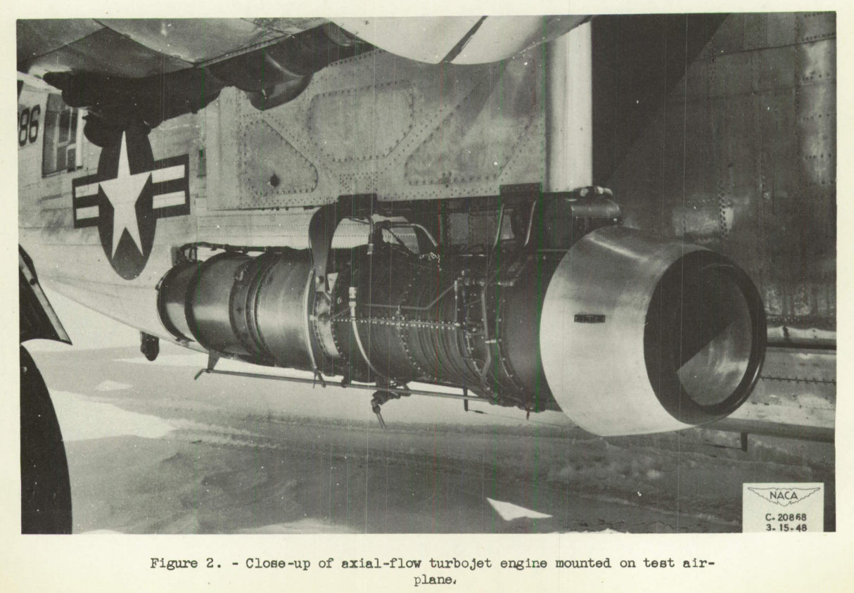
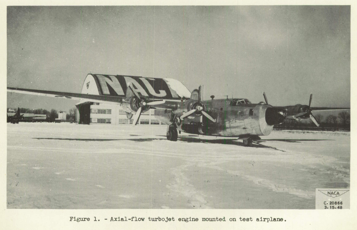
The 24C-2 turbojet engine was mounted on a four-engine bomber, which was provided with anti-icing equipment for the wings, the tail surfaces, and the propellers. A general view of the installation is shown in figure 1. A close-up view of the engine installation is shown in figure 2.

The turbojet engine used for this investigation has a 10-stage axial-flow compressor, a two-stage turbine, and an annular combustion chamber. The operating characteristics of the engine are as follows:
Maximum engine speed, rpm ..........12,000
Cruising engine speed, rpm .........11,000
Static-thrust rating, pounds .........2800
Maximum tail-pipe temperature, °F ....1220
Instrumentation was provided at the compressor outlet for calculation of compressor efficiency and at the tail-pipe outlet for calculations of air flow and thrust. Interstage static pressures were provided to determine the pressure distribution through the 10-stage compressor.
RESULTS AND DISCUSSION
Photographs taken after the icing flight are shown in figure 3. A front view of the ice formation on the engine inlet and the starter housing is shown in figure 3(a). The degree of ice accumulation on the engine inlet is indicated in figure 3(b). Ice accumulation on the inlet guide vanes is shown in figure 3(c).
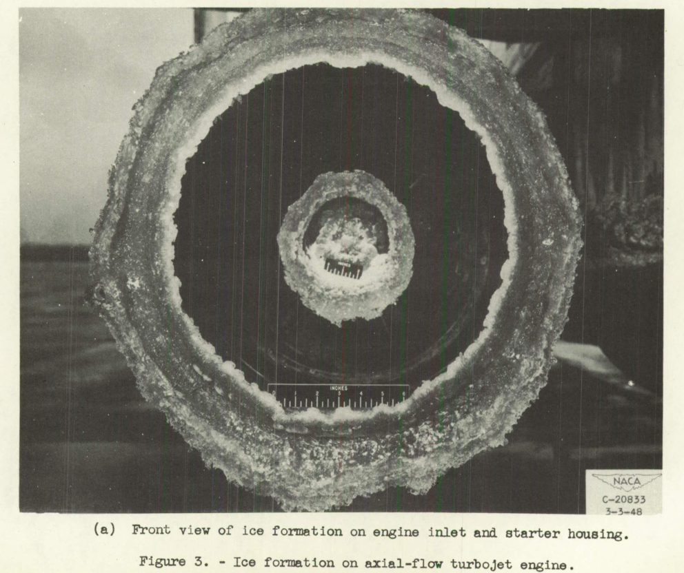
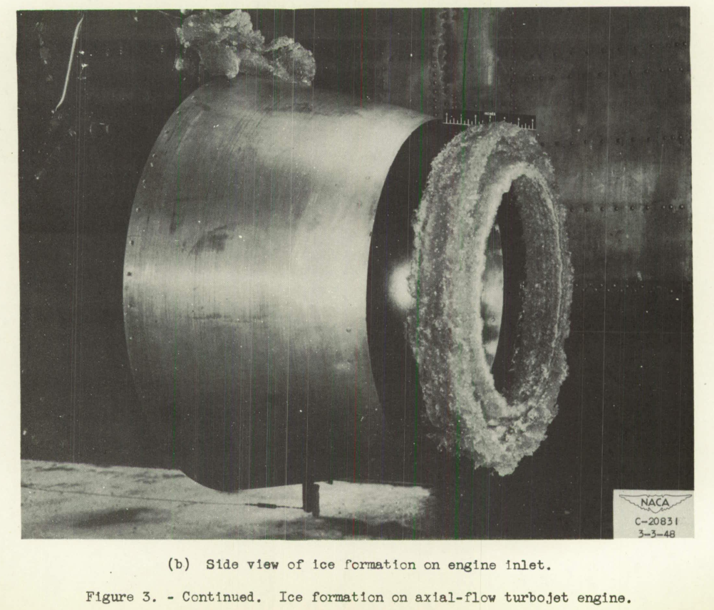
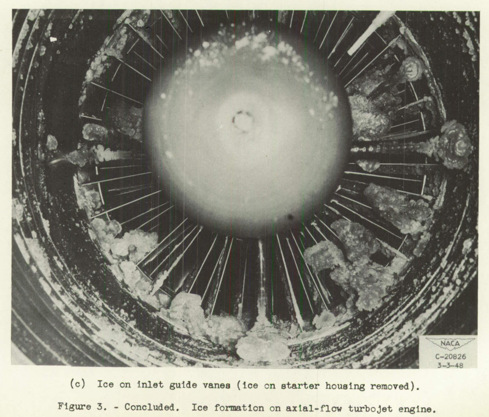
Visual inspection of the inlet indicated that ice had accumulated on the first-stage stator blades (fig. 3(c)), the second-stage stator blades, and the first-stage rotor blades. The ice formation on the first-stage rotor blades was concentrated at the leading edge and was approximately 1/8 inch thick. The ice formation on the second-stage stator blades was also concentrated at the leading edge and was approximately 1/32 inch thick and rather sporadic.
Inspection of the compressor rotor and stator blades revealed no damage to either from ice throw-off.
The effect of the ice formation on the engine thrust and tail-pipe temperature is shown in figure 4 as a function of time in the icing condition.
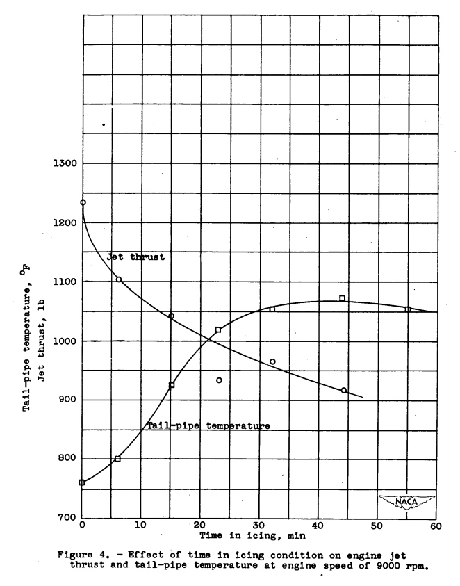
The engine was operated at a speed of 9000 rpm in an icing condition for approximately 1 hour. Engine data were taken before the icing cloud was entered and periodically during the encounter with the icing condition. At the end of 45 minutes, the engine thrust had decreased from 1234 to 910 pounds, a reduction of approximately 26 percent. After 45 minutes, the tail-pipe temperature had reached its maximum rise from 761° to 1065° F. At this point during the encounter, the tail-pipe temperature appeared to stabilize. The greatest decrease in thrust and increase in tail-pipe temperature appeared to occur in the first 15 minutes of the encounter.
A time history of the icing conditions encountered is given in figure 5, which shows the rate of icing, free-air temperature, drop size, and liquid-water content.
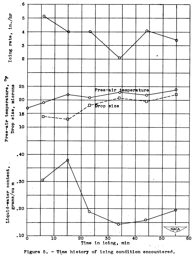
The icing rate varied from 5.1 to 2.1 inches per hour. The free-air temperature and the drop size showed a gradual increase during the encounter. The liquid-water content was highest during the first 15 minutes, reaching a peak value of 0.38 gram per cubic meter and decreasing to approximately 0.17 gram per cubic meter during the remaining 45 minutes. No general conclusions can be reached from these data because the icing conditions were relatively light and occurred at an average free-stream temperature only about 10° below the freezing point. The conduction of heat through the engine parts and the impact temperature rise on the rotor blades resulted in elevated blade-surface temperatures and minimized the effect of icing on engine performance. It is believed that at lower free-stream temperatures the effect on engine performance would be more severe. These data were obtained at an engine speed of 9000 rpm and no engine shutdown was required. If the engine had been operated at a speed of 12,000 rpm, however, a reduction in engine speed would have been mandatory.
Conclusions
The following results were obtained with an axial-flow turbojet engine from one icing encounter in natural icing conditions with an icing rate that varied from 5.1 to 2.1 inches per hour:
1. The tail-pipe temperature increased from 761° to 1065° F during an icing period of 45 minutes.
2. The engine jet thrust decreased from 1234 to 910 pounds during this same period.
3. Ice formations penetrated to the second-stage rotor blades.
Citations
This publication is cited by five publications, per scholar.google.com.
Related
This is part of the Engine Inlet Icing Thread.
Notes
-
Acker, Loren W.: Preliminary Results of Natural Icing of an Axial-Flow Turbojet Engine. NACA-RM-E8C18, 1948. ntrs.nasa.gov ↩