"Ice formation on the unheated leading edge, which may occur prior to activation of the heating system, was removed in 1 to 1 1/2 minutes by a hot-gas-flow rate that would be sufficient for normal anti-icing."
"Investigation of Porous Gas-Heated Leading-Edge Section for Icing Protection of a Delta Wing" 1
Abstract
SUMMARY
A tip section of a delta wing having an NACA 0004-65 airfoil section and a 60° leading-edge sweepback was equipped with a porous leading-edge section through which hot gas was bled for anti-icing. Heating rates for anti-icing were determined for a wide range of icing conditions. The effects of gas flow through the porous leading-edge section on airfoil pressure distribution and drag in dry air were investigated. The drag increase caused by an ice formation on the unheated airfoil was measured for several icing conditions. Experimental porous surface- to free-stream convective heat-transfer coefficients were obtained in dry air and compared with theory.
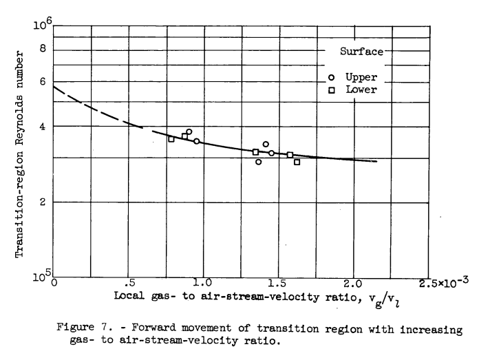
Adequate icing protection was obtained at all icing conditions investigated. Savings in total gas-flow rate up to 42 percent may be obtained with no loss in anti-icing effectiveness by sealing half tne upper-surface porous area. Gas flow through the leading-edge section had no appreciable effect on airfoil pressure distribution. The airfoil section drag increased slightly (5-percent average) with gas flow through the porous surface. A heavy glaze-ice formation produced after 10 minutes of icing caused an increase in section drag coefficient of 240 percent. Experimental convective heat-transfer coefficients obtained with hot-gas flow through the porous area in dry air and turbulent flow were 20 to 30 percent lower than the theoretical values for a solid surface under similar conditions. The transition region from laminar to turbulent flow moved forward as the ratio of gas velocity through the porous surface to air-stream velocity was increased.
Discussion
INTRODUCTION
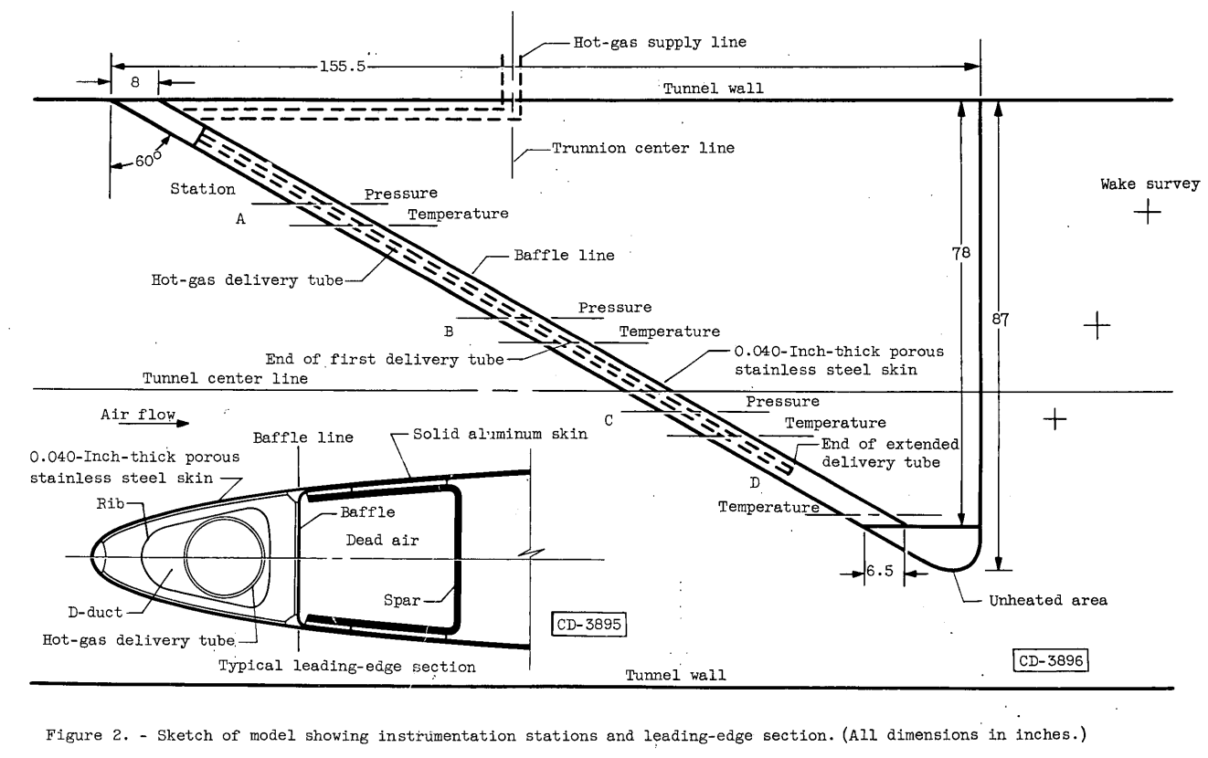
An airfoil may be protected in icing conditions by heating the leading-edge section so that all impinging water is evaporated. The required heat is usually obtained either by use of electric heating blankets or hot gas flowing through chordwise passages in contact with the inner surface of the wing skin. Increasing speeds of present-day aircraft have resulted in very large heating rates for this method of protection (ref. 1), requiring either large generating capacity for an electric system or high gas-flow rates for a gas-heated system. One means of reducing these heating requirements is by the use of a cyclic de-icing system. Research on such systems (refs. 2 and 3) has shown a reduction in heat requirement over continuous heating systems. For a high-speed thin-wing aircraft, considerations of available space, weight, complexity, and limited time in icing may require the use of a continuous heating system in spite of the higher heating requirements. The required surface heat release may be achieved in an economical manner by using a porous-metal leading-edge section through which hot gas is bled. Since the porous metal provides a large hot-gas contact area, the temperature of the porous surface is the same as that of the gas leaving the wing. With a conventional system having chordwise channels, the temperature of the gas leaving the channels is higher than the outer-skin temperature, and heat is wasted. Where space is limited, the .porous surface has the additional advantage of attaining a high heat-release rate in a relatively short heated length.
The use of a porous-skin heating system, however, may have effects on airfoil lift and drag. These effects may be measured experimentally to determine whether or not they are important. Contamination of the porous area by dust and insects may also be a problem. Periodic cleaning of the porous surfaces may be an acceptable solution.
Some experimental data on the use of a porous wall for heating are available. An experimental and theoretical investigation using a porous flat plate is reported in reference 4. A comparison between a porous-skin heating system for icing protection and a double-skin system with chordwise channels was made in reference 5 for one icing condition and indicates that the porous system is the more efficient of the two.
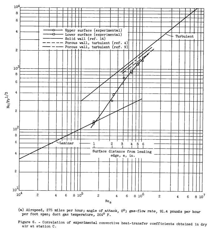
The associated field of transpiration cooling, wherein air is used to cool a porous wall in contact with a hot gas, has received much greater attention, both experimentally and theoretically (refs. 6 to 10). The superiority of transpiration cooling over convection cooling is shown in reference 8. Heat-transfer coefficients for laminar and turbulent flow may be obtained from the transpiration-cooling literature and applied to the problem of porous-wall heating provided the surface to free-stream temperature difference is small. The transition region from laminar to turbulent flow usually must be located experimentally for a particular body.
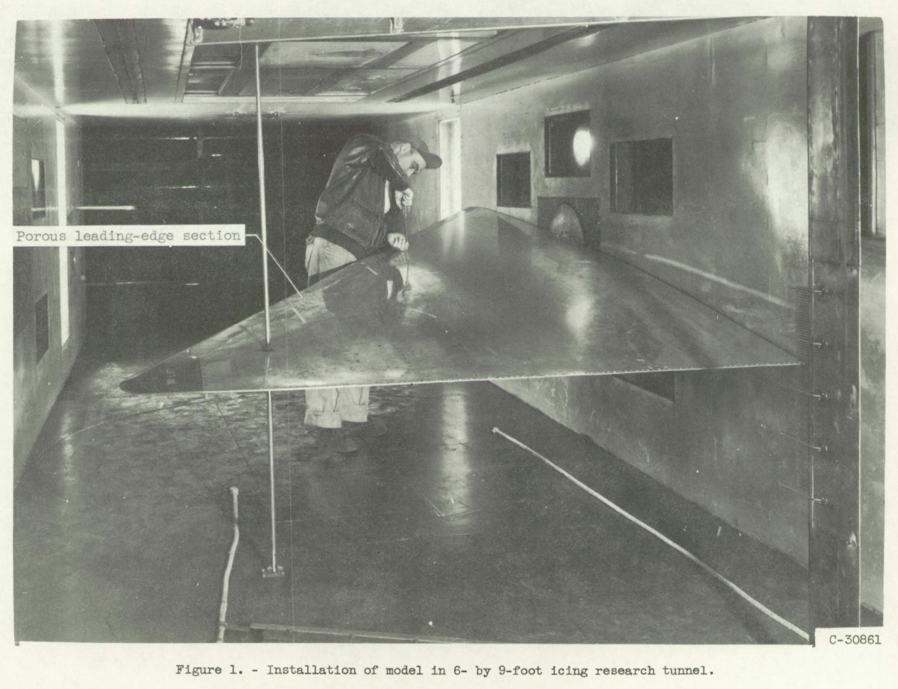
The present investigation was conducted in the NACA Lewis icing research tunnel using an airfoil model provided by an aircraft manufacturer. The influence of the porous system on airfoil pressure distribution, drag, and heat transfer was determined in dry air. Drag of the airfoil in icing with no heat was investigated to establish the need for icing protection. Heating requirements of the porous system for anti-icing were determined, and system performance was observed for a wide range of icing conditions. The de-icing characteristics of the porous leading-edge system were investigated briefly.
Selected figures illustrate key parts of the study:

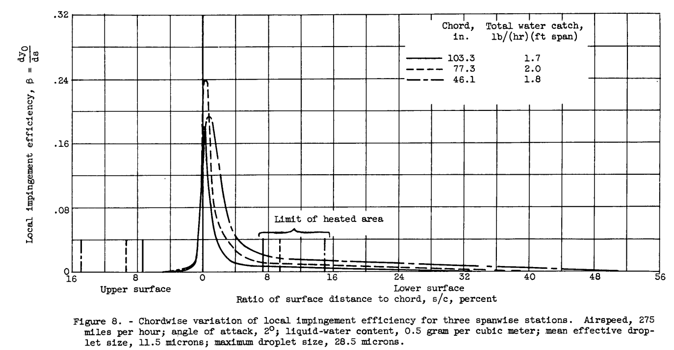
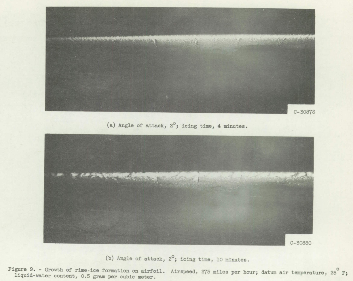
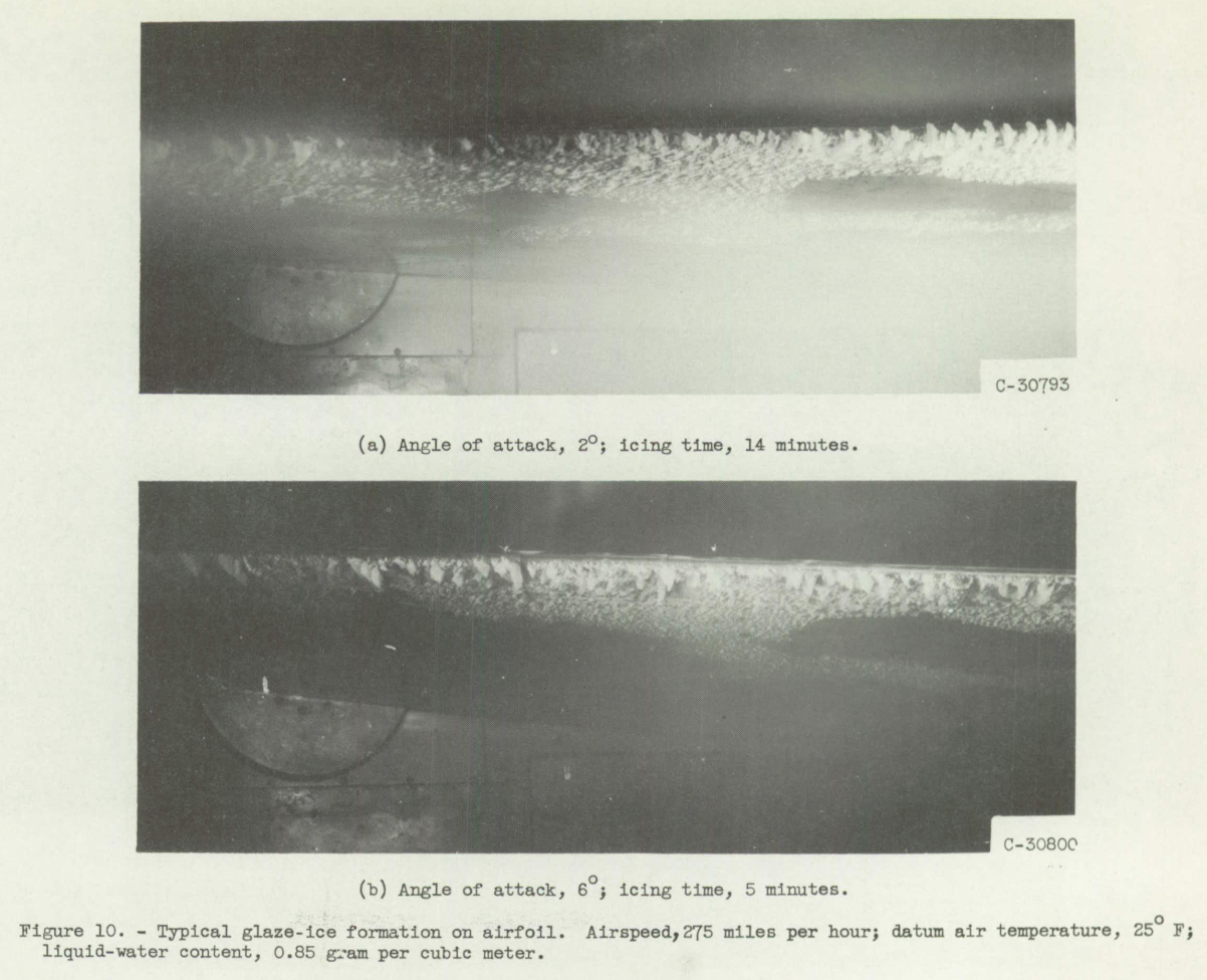
Conclusions
SUMMARY OF RESULTS
The results of an investigation of a porous gas-heated leading-edge section for icing protection of a delta wing may be summarized as follows:
1. Satisfactory anti-icing protection was obtained at all conditions investigated. A gas-flow rate of 143 pounds per hour per foot span with an entrance gas temperature of 496° F was sufficient for protection at the following condition: airspeed, 275 miles per hour; datum air temperature, 0° F; angle of attack, 2°; and liquid-water content, 0.4 gram per cubic meter.
2. Ice formation on the unheated leading edge, which may occur prior to activation of the heating system, was removed in 1 to 1 1/2 minutes by a hot-gas-flow rate that would be sufficient for normal anti-icing.
3. A full-span insulated hot-gas delivery tube should be provided to minimize the spanwise gas-temperature loss.
4. For positive angles of attack, a saving in total gas-flow-rate for anti-icing of 31 to 42 percent may be obtained with no loss in anti-icing effectiveness by sealing half the upper-surface porous area.
5. Gas flow through the porous leading-edge section had no appreciable effect on airfoil pressure distribution. Sealing the porous area did not affect the airfoil pressure distribution.
6. Gas flow through the porous area sufficient to provide icing protection caused a slight increase in airfoil drag (5-percent average) in most cases. Sealing the porous area did not change the airfoil drag. 7. The section drag coefficient of the unheated airfoil increased from 0.0066 to 0.0106 (60 percent) in 10 minutes of icing at moderate liquid-water content. A heavy glaze-ice formation, formed at a high liquid-water content, caused an increase in section drag coefficient from 0.0065 to 0.0222 (240 percent) in 10 minutes.
8. The extent of laminar flow in dry air with gas flow was small; most of the heated area was in the transition region from laminar to turbulent flow. The transition region moved forward as the ratio of gas velocity through the porous surface to free-stream velocity increased. 9. Experimental convective heat-transfer coefficients in dry air and turbulent flow were approximately 20 to 30 percent lower than the theoretical values for a solid surface, while the theories of Friedman and Mickley predict for the same conditions a reduction of 10 to 15 and 20 to 25 percent, respectively.
Another "associated field" of the use of flow through a porous surface is laminar flow control. Air is drawn in through the porous surface to reduce the growth of the boundary layer, thus promoting laminar flow further along a surface than would happen otherwise, reducing drag.
As for ice protection, "Contamination of the porous area by dust and insects may also be a problem".
Providing ice protection for an airfoil with a porous surface could be done using heated air blown out through the surface, as in NACA-RM-E54I03. The use of Freezing Point Depressant Fluids has also been proposed.
Some examples:
-
HYLTEC Laminar Flow Systems Flight Tests: Flight Testing of Anti-Icing and Anti-Contamination Systems on the DLR Do228 Test Vehicle www.semanticscholar.org
-
Preliminary Design and System Considerations for an Active Hybrid Laminar Flow Control System www.semanticscholar.org
Citations
NACA-RM-E54I03 is cited two times per scholar.google.com.
I view this as under-appreciated, as the technology has had recent interest for providing ice protection to areas with laminar flow control.
This appears to be the first test of this ice protection technology.
Related
NACA-RM-E54I03 is also mentioned in
Uses of NACA-Era Icing Wind Tunnels
and
Calibration of the NACA Icing Wind Tunnels
See also the Ice Protection thread for several other methods of ice protection.
Notes:
-
Bowden, Dean T.: Investigation of Porous Gas-Heated Leading-Edge Section for Icing Protection of a Delta Wing. NACA-RM-E54I03, 1955. ntrs.nasa.gov ↩