"the contour plots indicate that cowl-lip disturbances are the more controlling factor"
"Total Pressure Distortion and Recovery of Supersonic Nose Inlet with Conical Centerbody in Subsonic Icing Conditions" 1
Abstract
Ice was formed on a full-scale unheated supersonic nose inlet in the NACA Lewis icing tunnel to determine its effect on compressor-face total-pressure distortion and recovery. Inlet angle of attack was varied from 0° to 12°, free-stream Mach number from 0.17 to 0.28, and compressor-face Mach number from 0.10 to 0.47. Icing-cloud liquid-water content was varied from 0.65 to 1.8 grams per cubic meter at free-stream static air temperatures of 15° and 0° F.
The addition of ice to the inlet components increased total-pressure- distortion levels and decreased recovery values compared with clear-air results, the losses increasing with time in ice. The combination of glaze ice, high corrected weight flow, and high angle of attack yielded the highest levels of distortion and lowest values of recovery. The general character of compressor-face distortion with an iced inlet was the same as that for the clean inlet, the total-pressure gradients being predominantly radial, with circumferential gradients occurring at angle of attack.
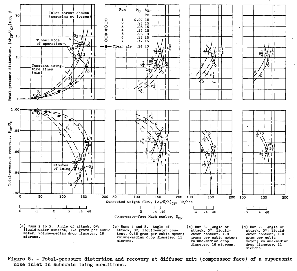
At zero angle of attack, free-stream Mach number of 0.27, and a constant corrected weight flow of 150 pounds per second (compressor-face Mach number of 0.43), compressor-face total-pressure-distortion level increased from about 6 percent in clear air to 12 percent after 21 minutes of heavy glaze icing; concurrently, total-pressure recovery decreased from about 0.98 to 0.945. For the same operating conditions but with the inlet at 12° angle of attack, a change in distortion level occurred from about 9 percent in clear air to 14 percent after 2 minutes of icing, with a decrease in recovery from about 0.97 to 0.94.
Discussion
APPARATUS
Model and Installation
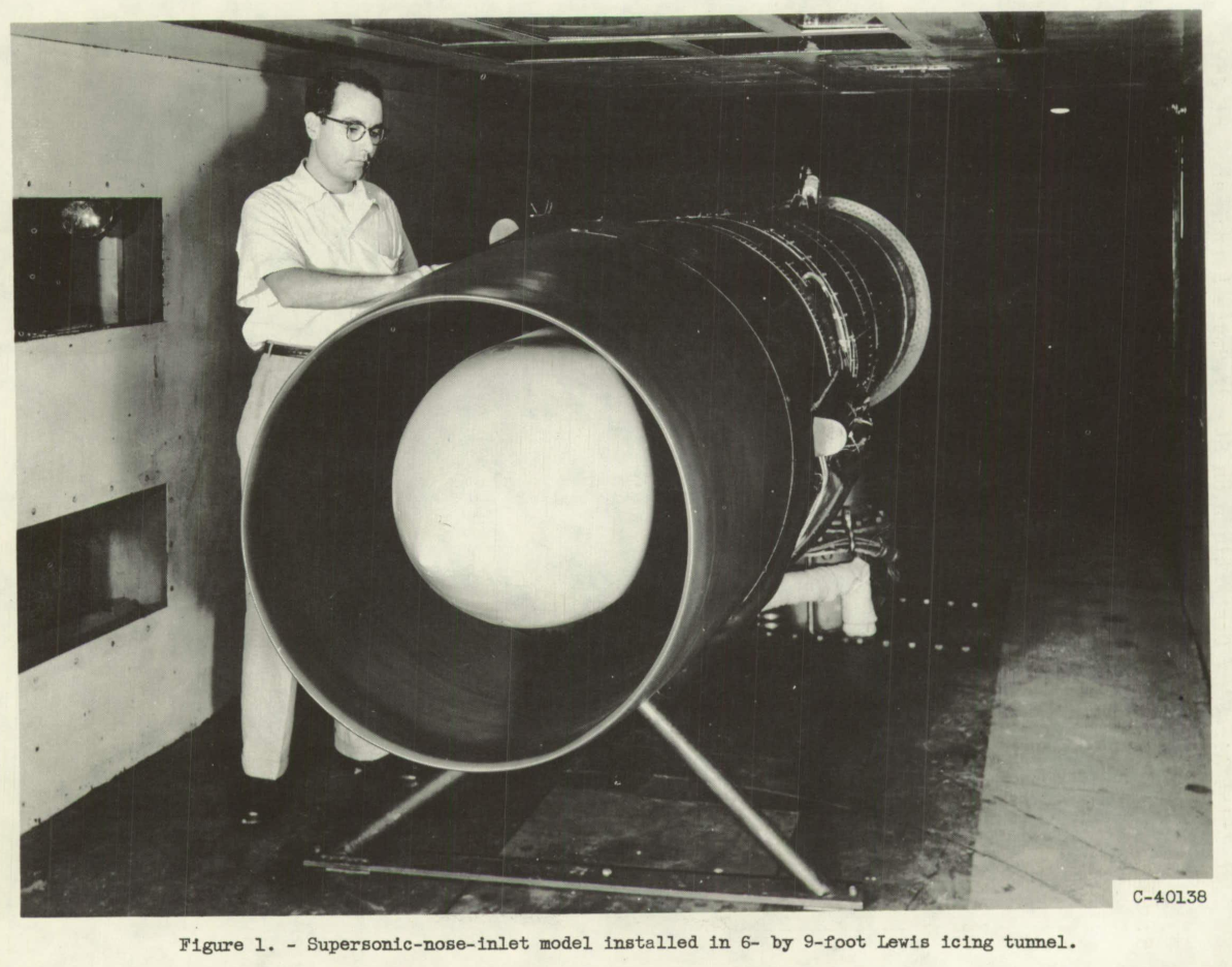
A front view of the supersonic-nose-inlet model installed in the 6- by 9-foot test section of the Lewis icing tunnel is shown in figure 1. The over-all length of the installation was about 20 feet, with a main support pedestal located near the midpoint. Additional support was provided by an A-frame just aft of the inlet lips. A prototype (full-scale) inlet was used for the first few feet of the external cowling and the first 7 feet within the inlet model (forward of the compressor-face station). The aft 13 feet of the installation contained the ejector nozzles and ducting used to simulate the pumping action of an engine compressor.
The conical centerbody was supported by three equally spaced swept-back struts mounted from the outer shell or cowling, as indicated by the schematic drawing of the inlet and afterbody in figure 2(a). The over-all top view of figure 2(a) shows the inlet at 12° angle of attack. Because of the model and tunnel size, only the forward half of the installation was at angle of attack relative to the free stream.
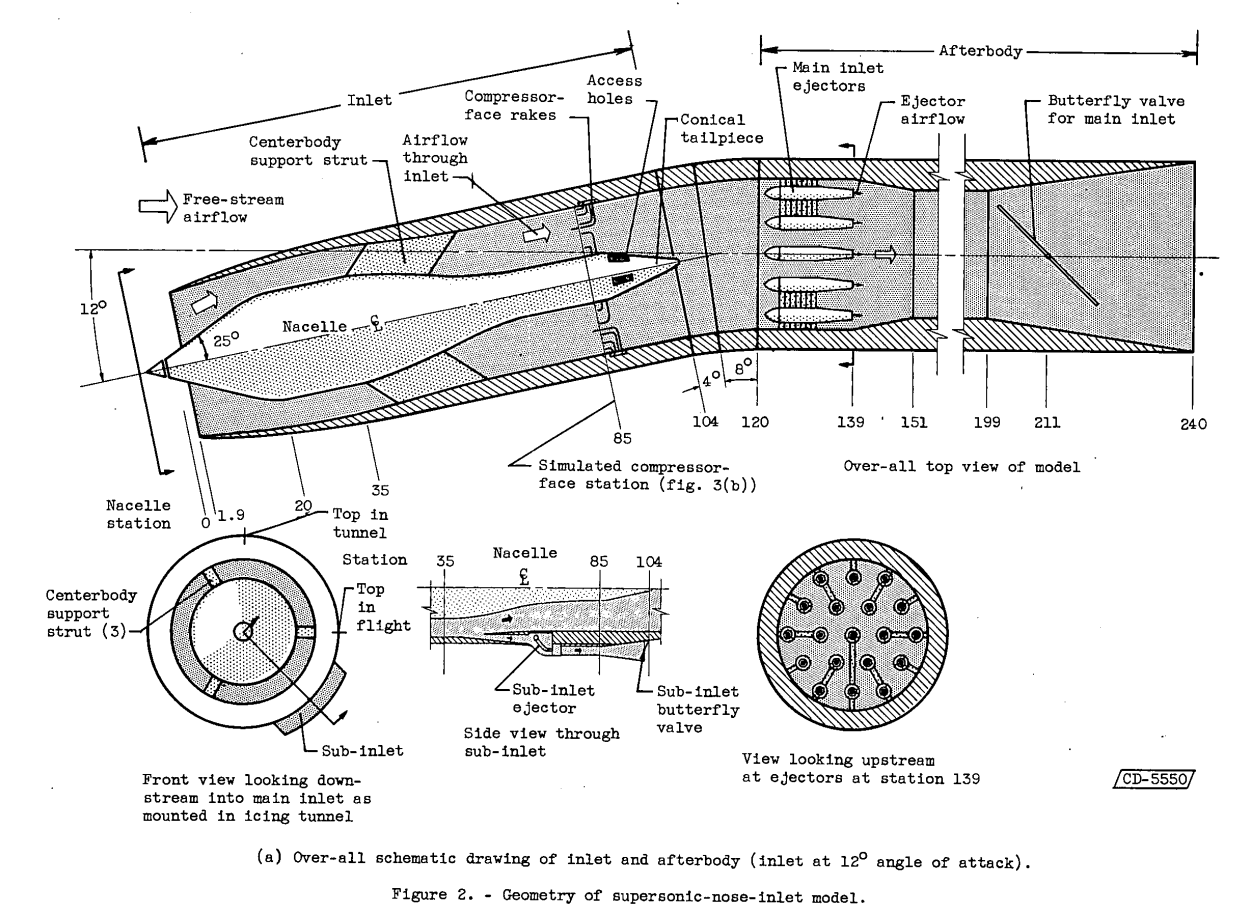
The front-view schematic drawing of the inlet shown in figure 2(a) indicates the positions of the three centerbody struts and the sub-inlet as mounted in the tunnel. This sub-inlet, which provides air for oil-cooling, is one of three included in the prototype design. A side view of the sub-inlet (located between stations 35 and 104) is also shown. Airflow through the sub-inlet is independently controlled by two ejector nozzles (one shown) and a butterfly valve. A front-view photograph of the inlet model showing the support struts and sub-inlet is given in figure 2(b).
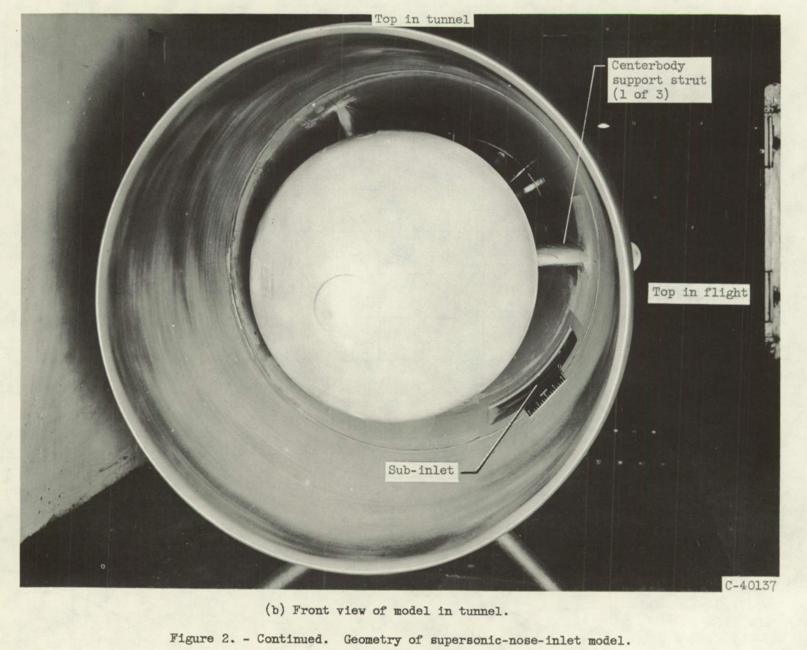
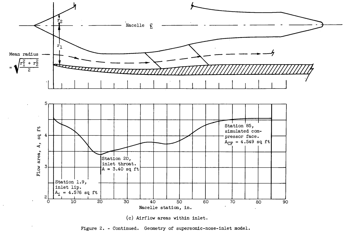
Figure 2(c) presents the annular flow areas within the main inlet from the cowl-lip station 1.9 to the compressor-face station 85. These flow areas at any nacelle station, which are calculated on the assumption that the airflow across the annulus is parallel to the mean radius at that station, account for the presence of the centerbody support struts. Significant airflow areas are: inlet lips (station 1.9), 4.576 square feet; inlet throat (station 20), 3.40 square feet; and compressor face (station 85), 4.549 square feet.
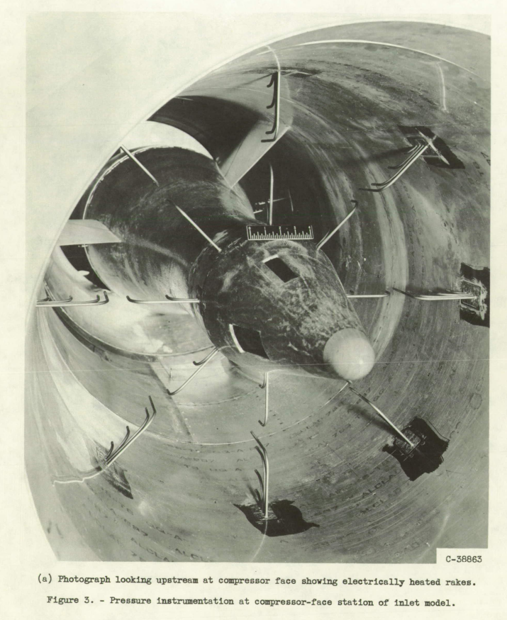
As shown in figure 3, model instrumentation consisted of 16 rake's (electrically heated coaxial pressuretubes) and 16 flush wall static taps, eight on the centerbody and eight on the cowl inner wall. All model instrumentation was at the simulated compressor face (station 85); a photograph looking upstream at this station is shown in figure 3(a).
ANALYSIS AND PRESENTATION OF DATA
The effect of mode of operation in evaluating compressor-face airflow distortion and pressure recovery resulting from iced inlet components is illustrated in figure 4. This figure is a schematic representation of typical total-pressure distortion and recovery data as a function of corrected weight flow. The dashed curves for zero icing time (clear air) indicate the usual trends of distortion increases and recovery decreases with increased corrected weight flow (refs 5 and 7). Similar but more pronounced trends are noted for the dashed curves for 5 minutes in icing (fixed free-stream icing condition). The solid lines connecting the symbols (number beside each data symbol denotes minutes of icing at a fixed free-stream condition) represent data obtained from a typical tunnel mode of operation. For the tunnel mode, corrected weight flow decreases with icing time; concurrently, distortion and recovery continue to increase and decrease, respectively. Generally, a change in the free-stream icing condition will shift the curves of constant icing time for all icing times greater than 0. Also indicated in figure 4 is the inlet-throat (station 20, fig. 2(c)) choking limit (assuming no losses).
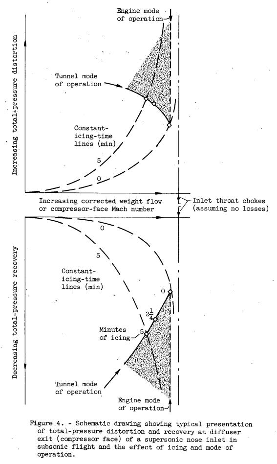
With an engine operating at a constant corrected engine speed, the curve for engine mode of operation would be vertical at a particular constant value of corrected weight flow (dotted line, fig. 4). The shaded areas in figure 4 emphasize the range of divergence between the tunnel mode of operation (solid line) and the engine mode of operation (dotted vertical line). Changes in distortion and pressure recovery with icing time are increased by the engine mode of operation as compared with the tunnel mode. By presenting data for total-pressure distortion and recovery in the form of figure 4, interpretation of results is not completely restricted to the tunnel mode of operation, and a reasonable approximation of losses at constant corrected weight flow (engine mode of operation) is possible.
RESULTS AND DISCUSSION
Total-pressure distortion and recovery as functions of corrected weight flow are presented in figure 5 for all conditions studied herein. Figures 5(a) to (d) depict four different free-stream icing conditions with the inlet model at zero angle of attack. For a particular icing condition, the effects of angle of attack are illustrated in figures 5(e), (g), arid (h), for angles of 12°, 8°, and 4°, respectively. For 12° angle of attack, figure 5(f) presents data for a less severe icing condition than that shown in figure 5(e). The effects of corrected weight flow, free-stream icing condition, icing time, angle of attack, and mode of operation are obtained from a study of the data in figure 5. These effects are isolated and presented separately in the following discussion.
Icing Results
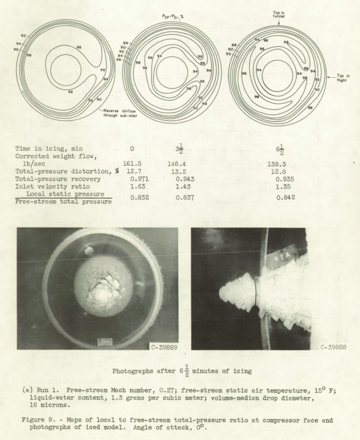
The glaze-ice formations of run 1 are considerably larger than the rime-ice formations of run 4 and cause more disturbances to the inlet airflow, as reflected in the tabulated values of distortion and recovery and in the corresponding total-pressure-contour maps. Except for the local flow disturbances caused by the 3 o'clock support strut and the sub-inlet between the 4 and 5 o'clock positions previously discussed, the total-pressure contours are generally symmetrical, with radial gradients or distortion. At zero icing time the pressure gradients are most severe near the cowl wall. With time in icing the gradients increase near the cowl and centerbody and extend farther into the flow annulus, thereby reducing the area of high pressure recovery. The photographs and pressure-contour maps for glaze-icing run 1 in figure 9(a) are typical of those obtained for the other glaze-icing runs 2 and 6 (figs. 5(a) and (c), respectively). Likewise, figure 9(b) for run 4 is typical for the other rime-icing runs 5 and 7 (figs. 5(b) and (d), respectively).

Comparison of a glaze and a rime cowl-lip ice formation at nearly the same inlet velocity ratio is illustrated by figures 11(a) and (c). The smoother rime formation of figure 11(c) results in distortion and pressure-recovery values of [15 percent] and [0.945], respectively, an improvement over the comparable glaze formation values of [20 percent] and [0.915]. Compressor-face distortion and recovery for the rime ice formation (fig. 11(c)) are also an improvement over those obtained at the higher inlet velocity ratio with glaze ice (fig. 11(b)). The distortion and pressure-recovery values also include the effects of ice formations on the centerbody and support struts, while only cowl-lip ice is illustrated by the sketches. However, the contour plots of figure 9 indicate that cowl-lip disturbances are the more controlling factor.
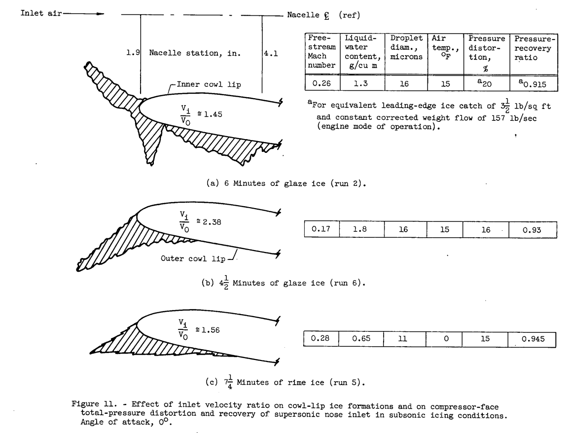
Note "cowl-lip disturbances are the more controlling factor".
Conclusions
Concluding Remarks
Compressor-face total-pressure distortion and recovery are closely related to the particular design and operation of an inlet in clear air or in icing, and the type and location of inlet ice are important factors. Under certain icing and operating conditions the data herein indicate that ice formations on an engine inlet cause increased distortions that may result in significant thrust reductions and surge or stall problems, based on previous data. These penalties to engine performance may be approximated from the data presented herein for an engine with known distortion tolerance.
Although there was little breakoff of ice from the inlet components during these studies, the danger of ice breakoff and ingestion by the engine exists and should be considered with reference to elimination of an inlet icing-protection system. Thus, the possible penalties regarding engine performance and engine damage accruing from inlet icing are such as to favor icing protection for the inlet unless the particular configuration or flight plan reduces the risks of no protection to an acceptable level.
SUMMARY OF RESULTS
The effects on compressor-face total-pressure distortion and recovery of ice formations on the unheated supersonic nose inlet studied are summarized as follows:
1. The addition of ice to the inlet components resulted in increased distortion levels and reduced pressure recovery compared with clear-air values, the losses increasing with time in icing.
2. The compressor-face flow losses were greatest for the higher corrected weight flows and angles of attack and for glaze-ice formations. After a few minutes of glaze icing the effects of angle of attack on distortion level and recovery are minimized.
3. The general character of compressor-face distortion with an iced inlet was the same as that for the clean inlet except for steeper pressure gradients (distortion patterns). The pressure gradients with the inlet studied were predominantly radial, with circumferential gradients occurring at angle of attack.
4. From a constant-corrected-weight-flow (150 lb/sec, compressor-face Mach number of 0.43) interpretation of the tunnel data, total-pressure distortion increased from about 6 percent in clear air to 12 percent after 2 minutes of heavy glaze icing. Concurrently, total-pressure recovery decreased from about 0.98 to 0.945. These results are for the inlet studied at 0° angle of attack, a free-stream Mach number of 0.27, a liquid-water content of 1.3 grams per cubic meter, a droplet diameter of 16 microns, and a free-stream static air temperature of 15° F.
For comparable operating conditions but with the inlet at 12° angle of attack, a change in distortion level occurred from about 9 percent in clear air to 14 percent after 2 minutes of icing, with a decrease in pressure recovery from about 0.97 to 0.94.
For more recent turbofan designs, the engine itself may have few components heated for ice protection, but the engine inlet leading edges ("lips") generally do have ice protection.
Citations
NACA-RM-E57G09 is cited four times, per scholar.google.com.
Related
This is part of the Engine Inlet Icing Thread.
Notes
-
Gelder, Thomas F.: Total Pressure Distortion and Recovery of Supersonic Nose Inlet with Conical Centerbody in Subsonic Icing Conditions. NACA-RM-E57G09, 1957. ntrs.nasa.gov ↩