"... quick and reliable shedding of dangerous leading-edge ice caps and good heat utilization."
"Comparison of Several Methods of Cyclic De-Icing of a Gas-Heated Airfoil" 1
Abstract
Several methods of cyclic de-icing of a gas-heated airfoil were investigated to determine ice-removal characteristics and heating requirements. The cyclic de-icing system with a spanwise ice-free parting strip in the stagnation region and a constant-temperature gas-supply duct gave the quickest and most reliable ice removal. Heating requirements for the several methods of cyclic de-icing are compared, and the savings over continuous ice prevention are shown. Data are presented to show the relation of surface temperature, rate of surface heating, and heating time to the removal of ice.
Discussion
INTRODUCTION
The advent of high-speed, all-weather, jet-powered aircraft has emphasized the need for ice-protection systems that are light-weight, dependable, and automatic and that impose the least possible penalty on over-all aircraft performance. Anti-icing systems that evaporate all the impinging eater cause practically no increase in drag but, at high speeds, require-large rates of surface heating (ref. 1). These large heating requirements in an electric system call for a large generating capacity, which involves excessive weight; in a hot-gas system large flows of heated air are required, resulting in excessive thrust losses when the air is taken from the jet-engine compressor.
The large heating requirements associated with continuous anti-icing can be greatly reduced by the use, of a cyclic de-icing system, wherein only one spanwise segment of an airfoil is heated and de-iced at any given time. Intermittent heating and shedding of ice successively from many such segments in repeated cycles will permit a given heat flow to de-ice many times as much area as would be continuously anti-iced by the same flow. Consequently, a large reduction in the over-all heating requirement for an airfoil is realized.
Cyclic de-icing may be accomplished by using either electric or hot-gas heat sources. A typical electric cyclic de-icing system is described in reference 2. Heating requirements and resultant penalties for an aircraft with this type of ice-protection system are given in reference 1. Recently, efforts have been directed toward the development of hot-gas cyclic de-icing systems. The principal advantages of hot-gas cyclic de-icing are: The heat supply is readily available at the jet engines; the surface heating channels may be constructed integrally with the airfoil structure to permit a low weight-increase factor; and the operation of hot-gas systems is basically reliable, so that low maintenance costs result. The first experimental investigation of cyclic de-icing with hot gas is reported in reference 3, in which successful de-icing was accomplished with considerable savings of heat over continuous anti-icing.
The effect of a hot-gas cyclic de-icing system on aircraft performance has not been completely evaluated at present. However, the drag increases associated with hot-gas cyclic de-icing are presented in reference 4. Drag data obtained for an 8-foot-chord NACA 651-212 airfoil indicate that only moderate airfoil drag increases are to be expected from runback icing caused by cyclic ice removal and that after ice removal the drag returns almost to the bare airfoil drag. Only in severe icing conditions with high rates of water interception does the drag increase during the icing period exceed 15 percent.
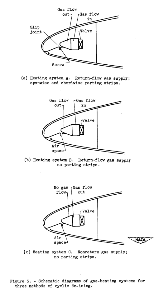
This investigation presents a comparison of heat requirements and ice-removal characteristics for several methods of cyclic de-icing with hot gas. The de-icing systems investigated differed principally with regard to the means of obtaining elevated gas temperatures at the surfaces to be de-iced and in regard to the use of ice-free parting strips in the stagnation region to facilitate ice removal. Because of the present lack of fundamental knowledge on cyclic de-icing processes, extensive data on heating rates, surface temperatures, and ice-removal times for various surface locations are presented to provide a basis for future analytical treatments. The investigation was made in the NACA Lewis icing research tunnel over a wide range of icing and operating conditions.
Three variations on the internal heating were considered.

Over-All Performance of Cyclic De-Icing Systems
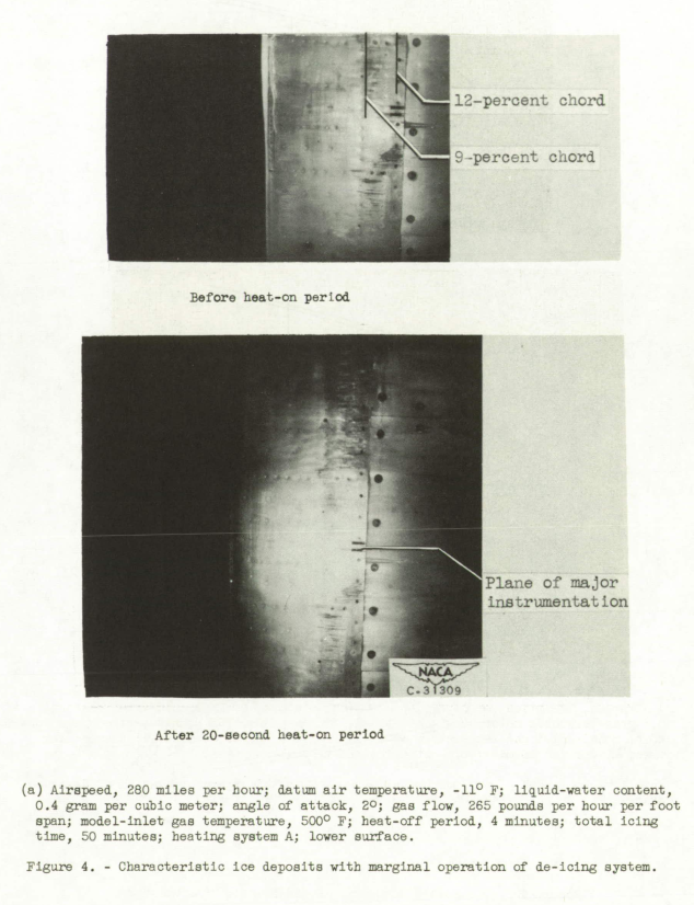
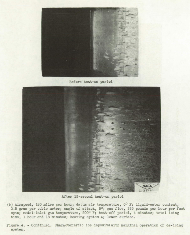
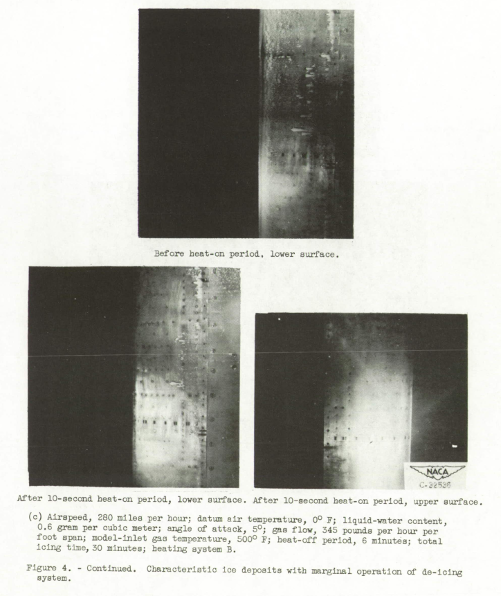
Typical ice formations with marginal de-icing.
Ice formations characteristic of marginal de-icing in various atmospheric and operating conditions are shown in figure 4 by photographs of the airfoil forward section before and after the heat-on periods. The difficulty and possible variance in establishing consistent marginal heating conditions are apparent from these photographs. Varying amounts of residual and runback icing can be seen in the photographs taken after the marginal heat-on periods. Negligible runback icing is shown in figure 4(a). In figure 4(b) runback deposits have begun to collect directly impinging droplets and are growing forward and outward. The deposits aft of the heated forward section are caused by impingement upon frost particles. The airfoil invariably frosted as soon as water sprays began, probably because of air-stream turbulence and supersaturation of the tunnel air, which is not the usual case in flight. Primary impingement icing on the upper surface was always completely removed, as shown typically in figure 4(c). Runback icing on the upper surface consisted of thin streaks of ice starting about 9 inches back from the leading edge. These runback streaks did not grow materially, because they shed sporadically during subsequent heat-on periods.
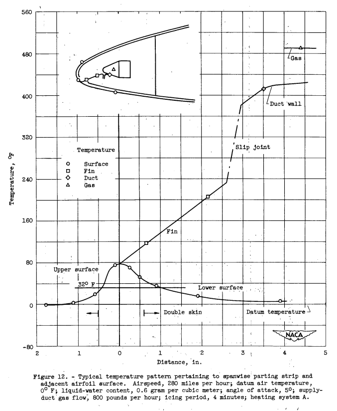
Parting-strip characteristics. - Data were obtained on the temperatare pattern associated with the spanwise parting strip used in system A. From these data the heat-flow rate through the conductive fin and the ice-free width of the parting strip may be determined. A typical temperature pattern is shown in figure 12, in which distances are measured along the heat paths from the juncture of the conductive fin and the external skin. These temperatures were taken after 4 minutes of icing and before cyclic removal. The temperature drop between the gas in the duct and the duct wall was small, representing approximately 20 percent of the total drop between gas and peak surface temperature. The temperature drop across the slip joint was approximately 35 percent of the gas-to-surface temperature differential. Without a slip joint, the same heat flow to the parting strip would be maintained with a thinner or longer conductive fin than was used herein. The fin length and thickness are of importance in transmitting the proper amount of heat flow for establishing a narrow parting strip.
The surface-temperature pattern reveals the heating effectiveness in the parting strip. The surface temperature should return quickly to the datum level on both sides of the parting strip to minimize heat losses by conduction along the surface. Such is the case on the upper-surface side of the parting strip, but the lower-surface temperature falls much more gradually. The arrows at approximately 1/2 inch from the center of the parting strip (fig. 12) indicate the start of the corrugated inner-skin passages. The added thickness and conductivity of the double-skin construction require a larger distance for the surface temperature to return to datum.
The width of the parting strip that is above 32° F prior to the heat-on period may be determined from the surface-temperature pattern (fig. 12), and it was found to be conveniently expressible as a function of the temperature ratio ( ts,max - 32 ) / ( ts,max - td ) shown in figure 13 for all conditions investigated.

Results
SUMMARY OF RESULTS From the present investigation of several methods of cyclic de-icing of a gas-heated airfoil, the following principal results were obtained:
1. For equivalent icing conditions and heating rates, when all ice-free parting strips were removed from a cyclic de-icing system, approximately 50 percent longer heat-on periods were required for marginal ice protection; when parting strips were removed and the return-flow (continuously heated) gas-supply duct was changed to a single-passage gas duct, an increase of approximately 85 percent in the heat-on periods was required. Removal of all parting strips reduced the spanwise drop in supply-gas temperature by approximately one-third.
2. The equivalent-continuous or heat-source requirement for marginal cyclic de-icing was nearly the same for heating systems with or without parting strips. The heat-source requirement was increased from 10 to 50 percent when continuous heating of the gas-supply duct was eliminated. 3. The heat-source requirement for cyclic de-icing was between one-fourth and one-tenth of the comparable heating requirement for continuous anti-icing.
4. The heating time required for ice removal was an inverse function of the heating rate; however, the surface temperature at ice removal appeared to be a random variation between 32° and approximately 100° F. The greatest external effect on the surface temperature during the de-icing period was caused by flows of water and melting ice over the surface.
5. Parting strips, insulation, and continuous heating of the gas-supply system were advantageous for quick and reliable shedding of dangerous leading-edge ice caps and good heat utilization.
Citations
Eight citations for this publication were found at scholar.google.com.
Related
See also the Ice Protection thread for several other methods of ice protection.
Notes
-
Gray, Vernon H., and Bowden, Dean T.: Comparison of Several Methods of Cyclic De-Icing of a Gas-Heated Airfoil. NACA-RM-E53C27, 1953. ntrs.nasa.gov ↩