"The air-heated-propeller installation tested would offer little or no protection to the leading-edge regions of the propeller"
"A Flight Investigation of the Thermal Performance of an Air-Heated Propeller"
Abstract
The thermal performance of an air-heated propeller, installed on a test airplane, was evaluated by observations of the ice-prevention properties of the propeller during flight in natural-icing conditions and by the collection of thermal data on the propeller during flight in clear air and in clouds at temperatures above freezing. The test propeller was equipped with hollow steel blades of a standard design which were altered to permit heated air to enter the blade cavities at the propeller hub and to leave the cavities at the blade tips. No provisions were made to control the distribution of air flow inside the blades.
The observations in natural-icing conditions together with the thermal test data indicate that little or no protection to the leading-edge region of the propeller blades would result during flight in severe natural-icing conditions. The observations in natural-icing conditions were limited in that only light-icing conditions were encountered; however, in these light-icing conditions ice accretions formed on the leading edges of the blades in the region of blade stations 30 to 40. The clear air and cloud tests showed the propeller blades to be inefficient heat exchangers in that more heat energy was discharged in the air flow leaving the propeller than was dissipated through the propeller-blade surfaces. The measured blade-surface temperatures indicated that inadequate heating was provided to the leading-edge region of the propeller and show the need of providing means to increase the heat flow through the leading-edge region of the blades.
Discussion
INTRODUCTION
During the past few years, research has been directed to provide protection for aircraft propellers during flight in natural-icing conditions by the application of heat to the propeller blades. One means of a~plying heat has been through the use of electrically heated, rubber blade shoes placed over the leading edges of the propeller blades (reference 1). These shoes, however, in their present state of development have some effect (although small) on the aerodynamic performance of the propeller, require frequent servicing, and require the availability of a suitable electrical power supply. In an attempt to provide a more simple system, and make use of the heat content of the airplane engine exhaust gases, one of the well known propeller manufacturers constructed an air-heated propeller. This propeller was equipped with hollow steel blades of a standard design. It had provisions for inducting heated air into the blade cavities at the propeller hub and of disposing of it through discharge nozzles located at the blade tips. No provisions were made for controlling the distribution of the heated air in the blade interiors.
The purpose of the present investigation was to evaluate the thermal performance of this alr-heated propeller. The investigation consisted of flight tests in natural-icing conditions during which the ice-protection properties of the propeller were observed and flight tests in clear air and in clouds at temperatures above freezing during which thermal data on the propeller were obtained.
The investigation was conducted by the Ames Aeronautical Laboratory of the National Advisory Committee for Aeronautics. The flights in natural-icing conditions were conducted from the Army Air Forces Ice Research Base, Minneapolis, Minn., during the winter 1944-45; and the remainder of the tests were conducted at the Ames Aeronautical Laboratory, Moffett Field, Calif., in the summer of 1945.
DESCRIPTION OF EQUIPMENT
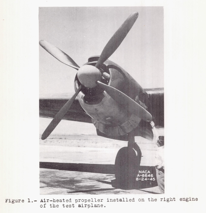
The test propeller, a four-blade, 14-foot-diameter, air-heated propeller was installed on the left engine of a test airplane. A similar installation, which was provided on the right engine for subsequent tests, is shown in figure 1.
The operation of the propeller heating system is shown in figures 2 and 3.
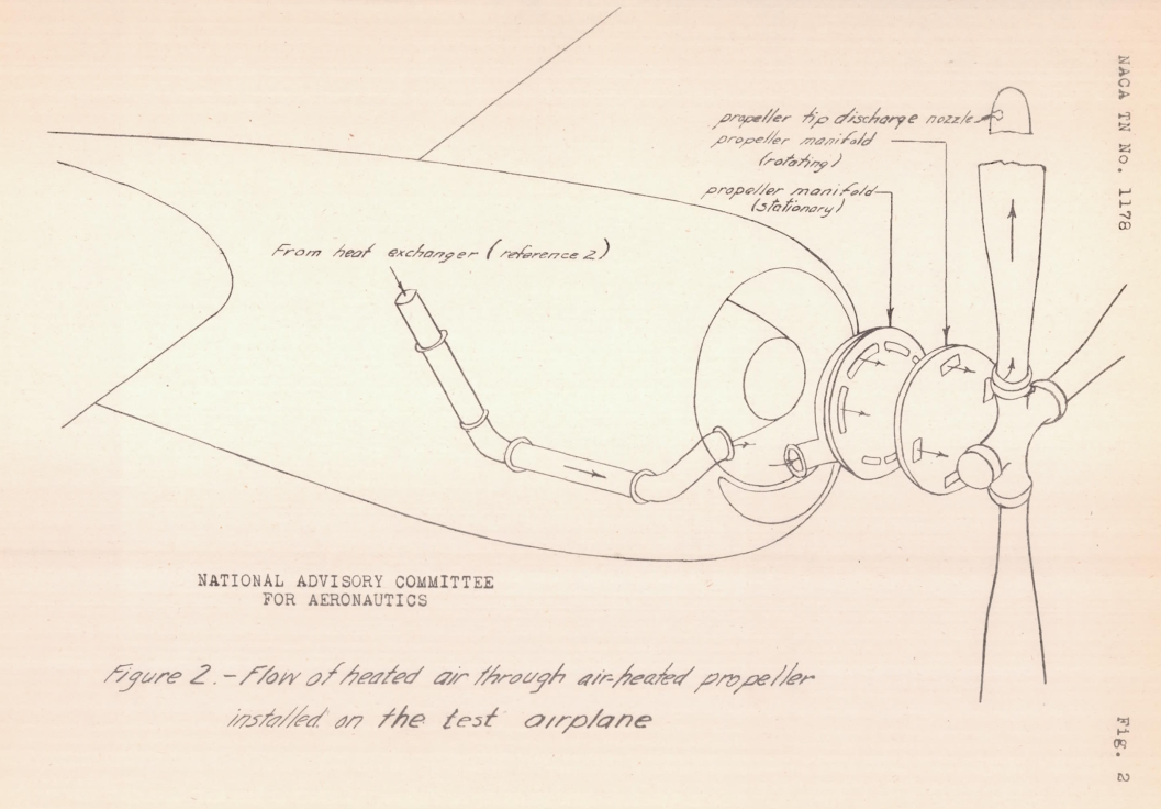
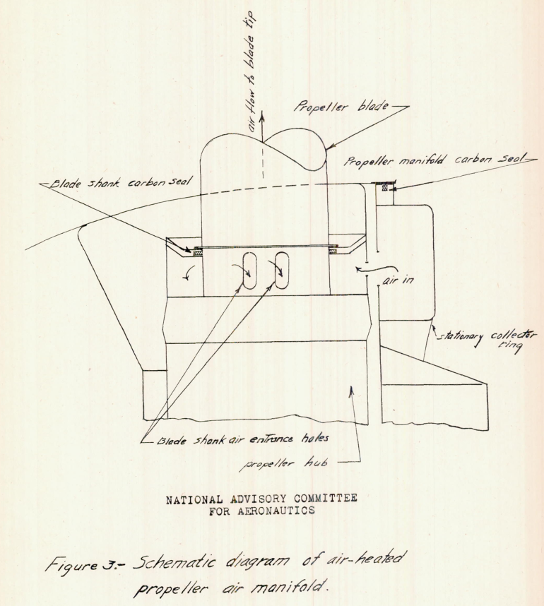
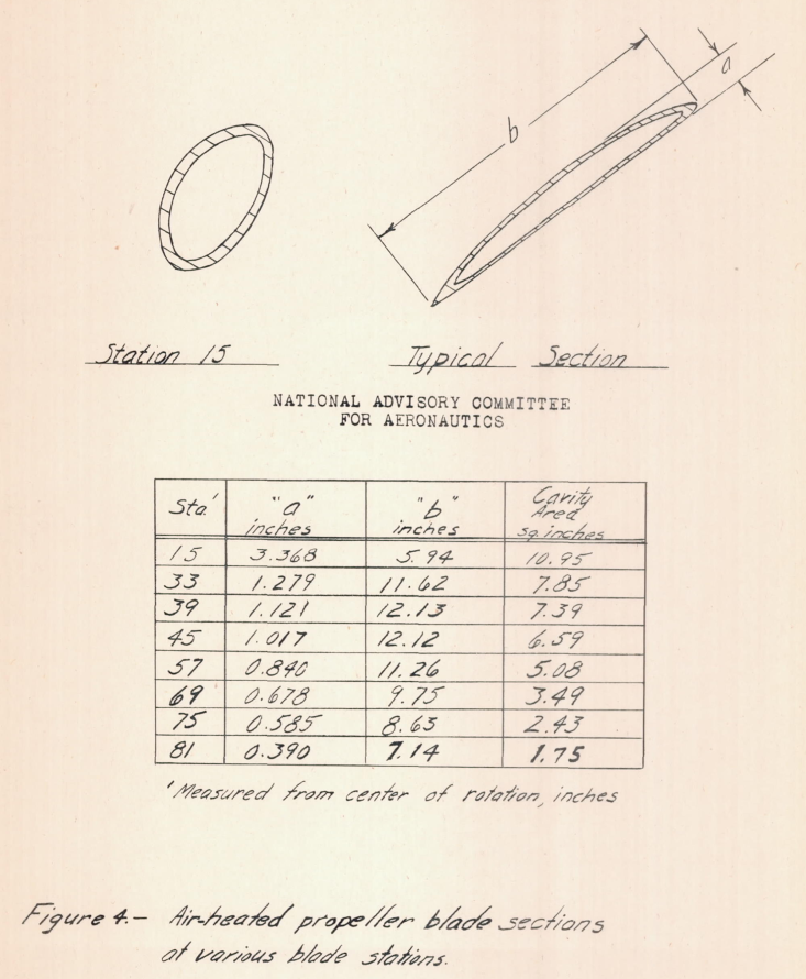
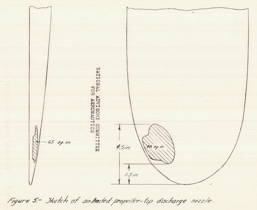
Ram air, heated by an exhaust-gas-air heat exchanger installation (described in reference 2) was ducted to the stationary part of the propeller air manifold. The heated air was then transmitted to the rotating part of the propeller air manifold, admitted to the blade cavity through holes in the blade shanks, and discharged through nozzles located at the blade tips. The air particles in the blade are subject to radial accelerations, due to the rotation of the propeller, which results in a pumping action. This pumping action together with the ram pressure at the heat exchanger induced the air flow through the system. In order to reduce the air leakage between the stationary and rotating parts of the propeller air manifold, and between the blade shanks and the rotating part of the propeller air manifold, carbon seals were provided as shown in figure 3. Tne approximate propeller-blade sections and a sketch of the propeller-tip discharge nozzles are given in figures 4 and 5, respectively. As employed herein, the term "station" denotes the radial distance from the center of rotation in inches. (See fig. 4.)
TESTS
For the flights in natural-icing conditions, the airplane was operated at the cruise conditions of 950 to 1000 propeller rpm (1900 to 2000 engine rpm) and indicated airspeeds of 150 to 160 miles per hour. During these tests measurements were made of the temperature and the rate of air flow delivered to the propeller. At all times the flow rate to the propeller was the maximum obtainable for the operating conditions. Visual and photographic observations were made of the ice-protection qualities of the propeller.
At the close of the period during which natural-icing conditions prevailed, the instrumentation on the rotating part of the propeller installation was installed and flight tests were undertaken in clear air and in clouds above freezing to obtain thermal data on the propeller. The tests were conducted at 2700 to 3900 feet pressure altitude, 160 miles per hour indicated airspeed, 950 propeller rpm, with a maximum rate of air flow to the propeller. These test conditions were established as being comparable to the operating conditions during the icing flights.
Measurements of the instrumented blade surface and tip air temperatures, as well as measurements of the heated-air-flow rates and the temperature of the air entering the propeller were recorded for these tests. One test run was made with the heated-air supply duct disconnected from the heat exchanger, and the propeller pumping free-stream air, in order to obtain an indication of the propeller-blade surface-temperature rises caused by adiabatic and friction heating resulting from the external and internal air flows.
RESULTS AND DISCUSSION
The observations made during flight in natural-icing conditions are presented in table I.
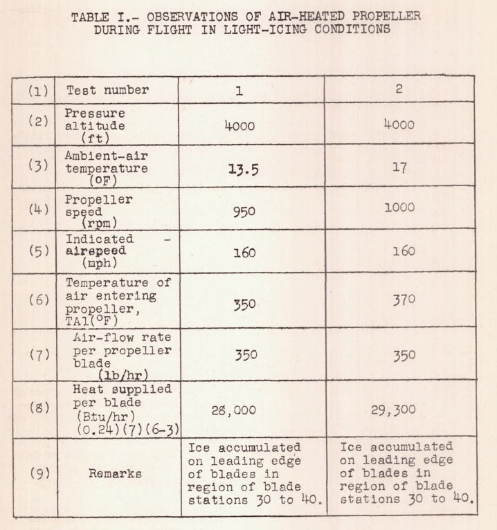
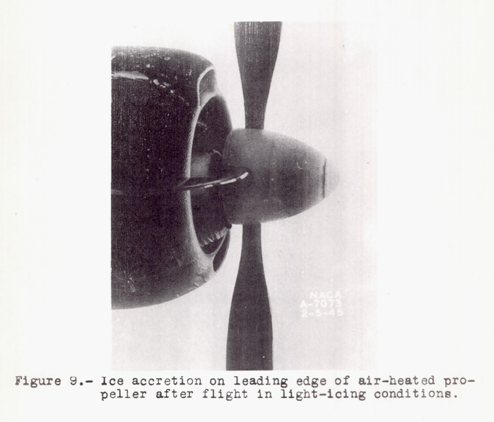
These observations were limited in that only light-icing conditions were encountered. Light-icing conditions are defined as those in which an unprotected airplane could sustain flight almost indefinitely. These results show, however, that even in these light-icing conditions, ice accumulated on the leading edge of the propeller blades in the region of stations 30 to 40 as shown in figure 9. No ice formation on the blades aft of the leading-edge regions was observed during the tests.

The blade-surface temperatures of table II have been plotted as temperature distributions in figure 10. The temperature distribution (above ambient-air temperature) obtained during the dry-air tests with heated air flow to the propeller is shown in figure 10(a).
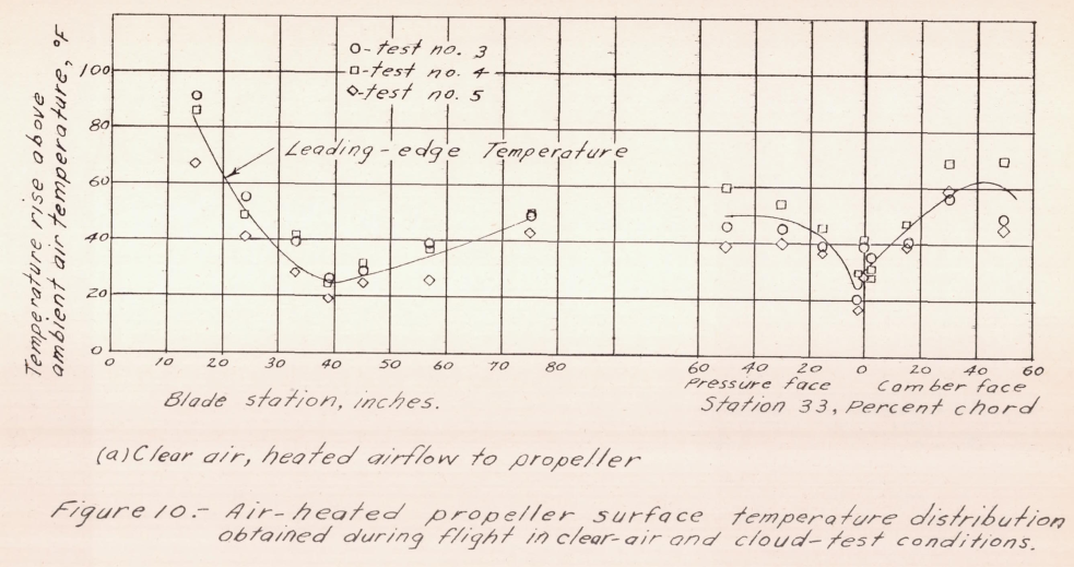
In figure 10(c) the mean curve of figure 10(a) is compared with the data obtained during flight in clouds. In this plot, the cloud data have been plotted as actual temperatures and the curve of figure 10(a) has been placed with respect to the ambient-air temperature of the cloud test. This method of plotting was used because the factors of wet-air kinetic heating of the blade surfaces and evaporization of water from the blade surfaces are dependent on the actual surface temperatures of the blade. A detailed discussion of these factors is presented for a wing surface in reference 4. The data obtained in the clouds provided no temperature data beyond blade station 57. Also included in this figure is a plot of the theoretical leading edge temperatures due to kinetic heating based on equation 2 using wet air values of cpo This figure shows that the temperature rise of the blade due to air heating diminished to practically zero at station 57. The leading edge temperature rises above ambient air temperature shown in this figure are very low (less than 10° F from station 35 to 57). This accounts for the fact that ice was observed to form on the leading edge regions of the propeller blades during flight in light natural icing conditions.
Reference 4 is:
- Hardy, J. K.: An Analysis of the Dissipation of Heat in Conditions of Icing from a Section of the Wing of the C-46 Airplane. NACA-TR-831, 1945. (Formerly NACA-ARR-4I11a.) ntrs.nasa.gov
> review: NACA-TR-831
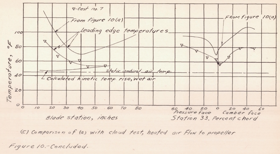
Application of the analysis of reference 4 to the present tests indicates that the blade-surface temperature rises above ambient-air temperature during the flights in light-icing conditions were probably greater than those experienced during the flight in clouds because the lower ambient temperature in the former tests would result in increased kinetic heating (lower cp) and a reduction in evaporative cooling.
The test data indicate that the temperature rise of the leading edges of the propeller blades could be expected to provide only limited ice prevention in flight-natural-icing conditions and therefore it may be concluded that little or no protection would be provided to the leading-edge regions of the blades in severe icing conditions.
Conclusions
The results of the thermal performance tests of an air-heated propeller indicate the following:
1. The air-heated-propeller installation tested would offer little or no protection to the leading-edge regions of the propeller during flight in severe natural-icing conditions.
2. The surface-temperature distribution is undesirable, and means should be provided to concentrate the heat in the leading-edge regions of the blades.
Complete ice protection for hot-air heated propeller blades was not achieved in this study.
Related
Other studies also found that unmodified, hollow blades were not efficient heat exchangers, but found that inserts to guide the internal flow improved performance:
-
NACA-RM-E50I08 "Icing Characteristics and Anti-Icing Heat Requirements for Hollow and Internally Modified Gas-Heated Inlet Guide Vanes"
> review: NACA-RM-E50I08 -
NACA-TN-2126 "Improvements in Heat Transfer for Anti-Icing of Gas-Heated Airfoils with Internal Fins and Partitions"
> review: NACA-TN-2126
Citations
This publication is cited three times, per scholar.google.com.
NACA-TN-1494 cites NACA-TN-1178.
Notes
-
Darsow, John F., and Selna, James: A Flight Investigation of the Thermal Performance of an Air-Heated Propeller. NACA-TN-1178, 1947. ntrs.nasa.gov ↩