"... will efficiently provide ice protection with a heat flow of feasible proportions"
"A Method for Estimating Heat Requirements for Ice Prevention on Gas-Heated Hollow Propeller Blades" 1
Abstract
SUMMARY
A detailed method is presented for determining the temperature and flow of heated gas necessary for ice prevention of hollow propeller blades in flight and icing conditions; The propeller blade is analytically divided into a number of short radial segments, which are successively treated as separate heat exchangers. Expressions for the total external and internal heat transfer are combined to determine the surface temperatures of each segment. The thermodynamic steady-flow equation is given for the internal gas-flow process and expressions are obtained for the radial variations of gas temperature and pressure within the blade. For a given initial gas temperature in the blade shank cavity, the minimum gas flow is determined, which will provide surface temperatures of at least 32° F everywhere on the heated portion of the blade. An expression for the required heat-source-input to the gas is included and a formula is given for calculating the required blade-tip nozzle area.
A discussion is included of the indicated benefits to be derived from certain alterations of the blade internal flow passage.
Discussion
INTRODUCTION
Thermal prevention of the formation of ice on aircraft propellers has been previously investigated by means of electrical and hot-gas heating, The heat requirements associated with the ue of external, electrically heated rubber blade shoes are analyzed in reference 1. Flight investigations of thermal systems using hot gas within hollow propeller blades have been reported in reference 2, and by Palmatier and Brigham of the Curtiss-Wright Corporation.
The present analysis was made at the NACA Cleveland laboratory to provide a method for predicting the hot-gas flow and the Initial gas temperature required for satisfactory ice prevention on hollow propeller blades. This method involves a system of progressive approximations considering successive radially disposed blade segments as separate heat exchangers. Account is taken of the heat required to raise the temperature of the intercepted free water to the-blade-surface temperature, the cooling effect of the evaporation of water, and the kinetic heating of the external-air boundary layer. The physical changes of the hot gas in flowing through the hollow blade are determined, in order to find the required tip nozzle area. The detailed analysis is applied to a typical propeller blade; for flight at two assumed operating conditions at the same icing conditions to illustrate the step-by-step procedure and to demonstrate typical results. A method of modifying the blade internal passage is suggested whereby the heating requirements may be reduced. for a given application of the hot-gas method of preventing ice on typical hollow propellers.
METHOD FOR DETERMINING DESIGN REQUIREMENTS
Description of Solution
The determination of the required gas-flow rates for a hot-gas type of anti-icing system on given aircraft propeller involves a tedious series of calculations. The information available at the present time is insufficient to determine quickly the maximum requirements for a given propeller operating through a range of flight and icing conditions. Individual calculations must be made for a complete series of selected, critical flight and icing conditions. The blade-tip nozzle area and the heat-source capacity are then calculated for the maximum requirements so determined.
The degree of approximation obtained through the use of the subsequent analysis will remain uncertain until more complete and reliable experimental data are available on propeller-blade external and internal heat-transfer coefficients, kinetic heating of wet air, heat losses due to evaporation of water, the extent of heat conduction in the blade metal, and the determination of minimum standards for ice prevention.
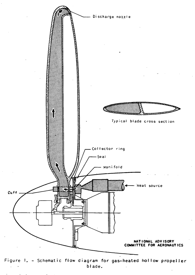
A schematic diagram of the heated-gas flow through a typical hollow propeller blade is illustrated in figure 1. The gas is first heated by a suitable heat source, enters a stationary transfer manifold, and then passes through a collector ring and cuffs fastened to the propeller hub and into the blade shanks. The hot gas then flows radially outward through the hollow blades, which may have internal radial partitions (fig. 1), to discharge nozzles in the blade tips.

The required gas flow, which is defined as the rate that will maintain the heated portion of a blade surface at temperature at or above 32° F, must be computed by trial. For conventional propeller-blade designs, the point of lowest calculated surface temperature will usually be at the stagnation point of a radial station near the hub. Under severe icing conditions, there is no great variation of calculated leading-edge surface temperature with propeller radius at the inboard, stations, although heat conducted radially outward from the blade hub will actually raise the surface temperatures at the inner radii. If the effect of this heat conduction from the blade shank does not extend too far along the blade at the leading edge, the use of the stagnation-point surface temperature at the innermost blade segment as the critical point for determining the required and gas flow will permit more rapid seldom will a complete progression with the trial values analysis of all segments be necessary.
Steps in Solution
For each set of flight and icing conditions the following step-by-step method of solution is suggested.
[There are eight pages of heat transfer and compressible fluid flow equations, plus 11 more pages in Appendices A through D]
NUMERICAL EXAMPLES
Flight and Icing Conditions
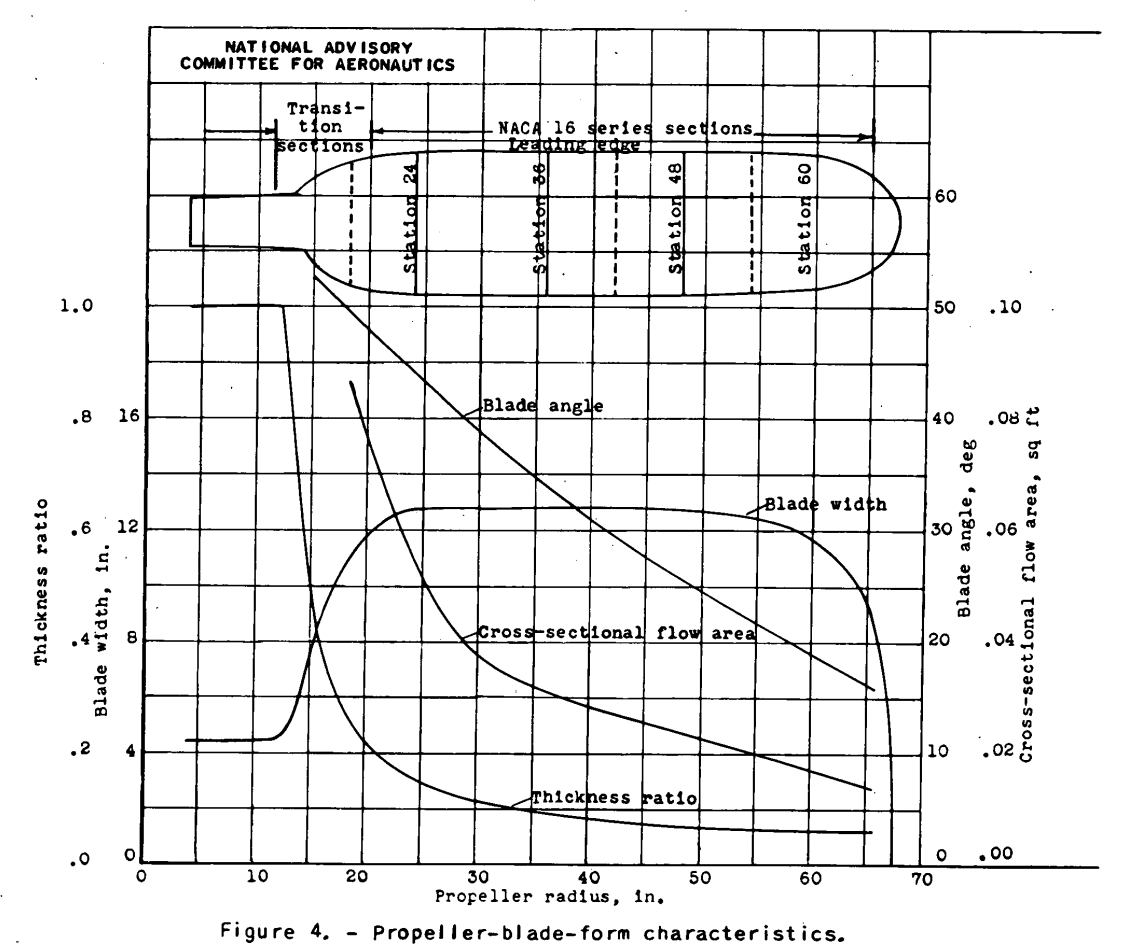
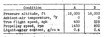
The procedure for determining the design requirements for a gas-heated propeller has been applied to a theoretical hollow steel propeller having blades with central radial ribs, as shown in figure 1. The propeller-blade-form characteristics are given in figure 4 and other pertinent data in table I. An assumption has been made that heated air enters the blade shanks from a collector ring through suitable orifices and passes radially outward through only the leading-edge cavity in the blades, as illustrated in figure 1. The blade was arbitrarily divided for convenience into four radial segments each 1 foot long starting at the 18-inch station. The radial stations for which the surface-temperature calculations were made were therefore at 24, 36, 48, and 60 inches. (See fig. 4.)
For more accurate results calculations nearer the hub may be necessary. A greater number of shorter radial segments may also be needed in regions where either the blade airfoil section or the internal flow area-changes rapidly with radius. For purposes of comparison, the calculations have been made for the two following operating conditions through the same icing condition:
Results
The general results are summarized as follows:

DISCUSSION
Thin-Skin Approximation
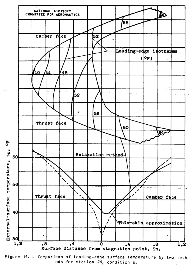
The largest source of error In this analysis is thought to be the thin-skin approximation used in the solution of external surface temperatures. This approximation makes use of two related assumptions. First, the value of Hg depends on the temperature differential (tg,d - ts), in which the temperature gradient through the blade metal assumed to be zero. This gradient and the error involved is usually small, except at the leading-edge region, for any propeller blade made of steel or metal with equal or higher thermal conductivity. Second, the heat balance employed in equation (22) is based on the assumption that the total heat transfer from the internal gas to the external air can be considered to be distributed uniformly and to pass only normally through suitable internal and external heat-transfer areas; that is, the blade metal is assumed to be infinitely thin and surface-wise heat conduction is neglected. The ratio of the teo heat-transfer areas is then used to determine the ratio of the local internal and external heat-transfer rates. The error involved in this assumption is thought-to be large inasmuch as the thermal conductivity of the blade metal is usually very high compared with the conductivity through the gas and air surface films. Surface-wise heat conduction within the blade metal is certain to reduce the temperature gradients indicated, by the variations of surface-film heat-transfer coefficients and changes in metal thickness.
The two foregoing errors can be eliminated from the analysis of the blade segments are studied using the "relaxation" method developed in reference 15. No attempt has been made to use this method because of the prodigious amount of time and effort involved. The method and a sample of the results to be expected from it are given in appendix E.
Suggested Technique for Reducing Heat Flows
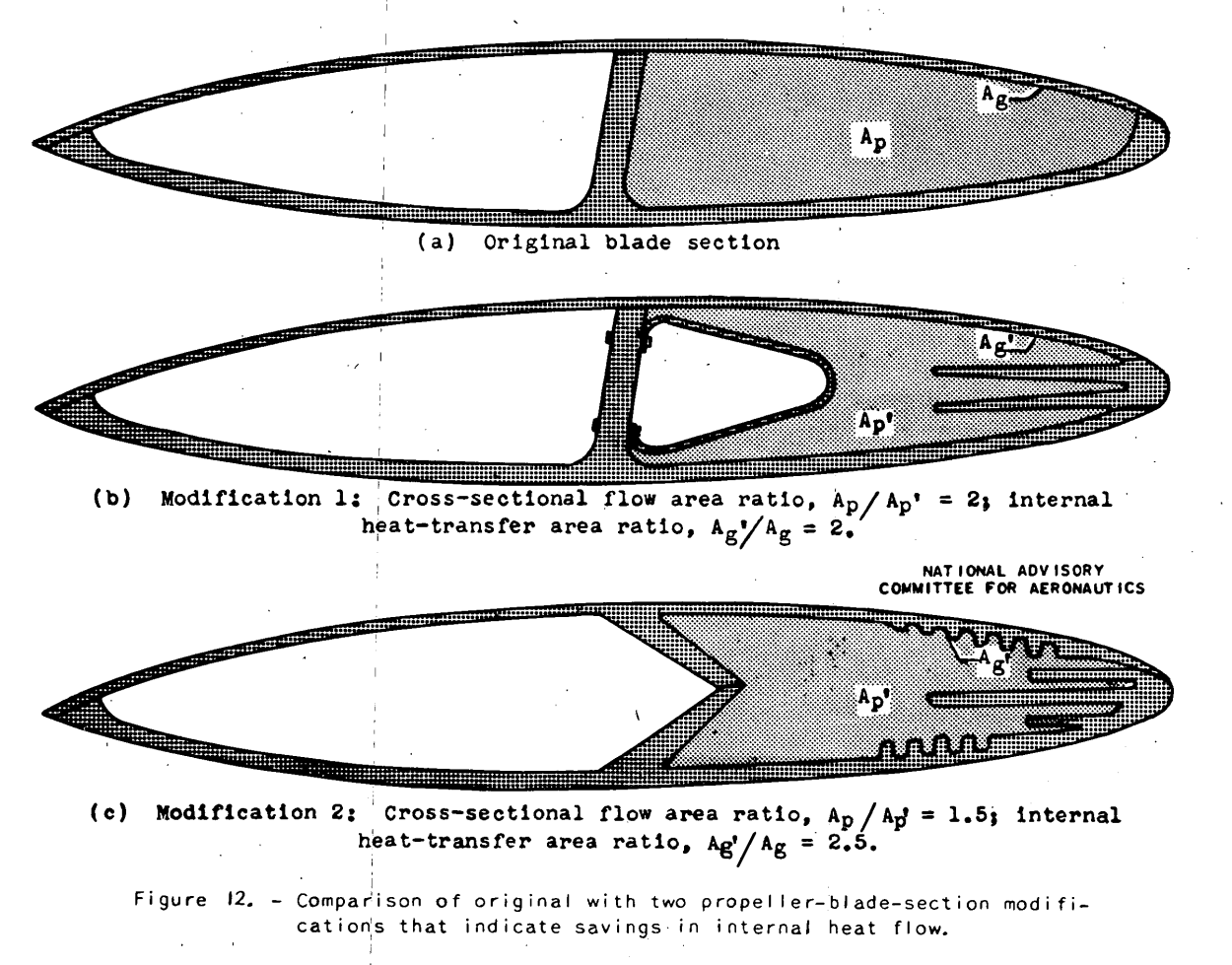
A method of reducing the required heat flow in a typical hollow propeller blade is suggested in which the internal flow passage is altered to attain a more economical distribution of heat transfer.
In summarizing these modifications, if the area of the internal flow passage is reduced and the internal heat-transfer area is increased, the same total heat transfer to the external surface can be maintained while the internal-gas flow is greatly reduced. A reduction of the flow lowers the internal velocity and the friction loss and thus raises the available internal pressure. When the flow is reduced, more heat is removed per pound of gas flow and, consequently, the gas temperature falls more rapidly and reduces the heat loss at the tip nozzle. Care should be taken with the internal heat-transfer area that some segments do not abstract such heat as to starve subsequent segments.
In addition to the foregoing reduction of heat flow, a better distribution of chordwise surface heat transfer can be accomplished by making the greatest increase of Internal heat-transfer area at the leading edge by the use of fins similar to those shown in figure 12. An accurate determination of the magnitude of the heat transfer resulting from these modifications requires that the whole problem be approached along the lines of the relaxation method as outlined in appendix E. All the Indications shown lead to the belief that a hollow propeller blade can be designed with modifications similar to those illustrated, which will efficiently provide ice protection with a heat flow of feasible proportions.
Conclusions
COMMENTS AND RECOMMENDATIONS
The method presented for estimating heat requirements for ice prevention on gas-heated hollow, propeller blades provides integrated means for determining the design requirements for ice prevention on gas-heated hollow propeller blades operating in any selected condition. Several of the suggested simplifications and other short methods can be used where conditions do not require a rigorous treatment. Solutions by trial are occasionally required, which are admittedly inconvenient, but become fairly rapid with increased familiarity.
Substantiation of several formulas, upon which this method is based, by experimental measurements in actual icing conditions is recommended. A relaxation analysis of the whole propeller blade should be made to determine the effect of leading-edge internal ribs and the exact heat transfer normally, radially, and chordwise through the blade metal.
Citations
This publication is cited ones, per scholar.google.com.
The single citations is:
Potapczuk, Mark G.: “Aircraft Icing Research at NASA Glenn Research Center.” Journal of Aerospace Engineering 26 (2013): 260-276.
Related
NACA-TN-1494 cites NACA-TN-1178.
See also Propeller publications by Porter Perkins
Notes
-
Gray, Vernon H., and Campbell, B. G.: A Method for Estimating Heat Requirements for Ice Prevention on Gas-Heated Hollow Propeller Blades. NACA-TN-1494, 1947. ntrs.nasa.gov ↩