"Complete icing protection for inlet guide vanes of a turbojet engine could not be achieved"
"Investigation of Aerodynamic and Icing Characteristics of Water-Inertia-Separation inlets for Turbojet Engines" 1
Abstract
SUMMARY
The results of an investigation of several internal water-inertia-separation inlets consisting of a main duct and an alternate duct designed to prevent automatically the entrance of large quantities of water into a turbojet engine in icing conditions are presented. Total-pressure losses and icing characteristics for a direct-ram inlet and the inertia-separation inlets are compared at similar aerodynamic and simulated icing conditions.
Complete ice protection for inlet guide vanes could not be achieved with the inertia-separation inlets investigated. Approximately 8 percent of the volume of water entering the nacelles remained. in the air passing into the compressor inlet. Heavy alternate-duct-elbow ice formations caused by secondary inertia separation resulted in rapid total-pressure losses and decreases in mass flow. The duration in an icing condition for an inertia-separation inlet, without local surface heating, was increased approximately four times above that for a direct-ram inlet with a compressor-inlet screen. For normal nonicing operation, the inertia-separation-inlet total-pressure losses were comparable to a direct-ram installation. The pressure losses and the circumferential uniformity of the mass flow in all the inlets were relatively independent of angle of attack. Use of an inertia-separation inlet would in most cases require a larger diameter nacelle than a direct-ram inlet in order to obtain an alternate duct sufficiently large to pass the required engine air flow at duct Mach numbers below 1.0 at the minimum area.
Discussion
INTRODUCTION Turbojet-engine ice protection by means of an inlet designed to separate the free liquid water from the intake air by waterNACA RM E50E03 inertia separation is shown to have possibilities in reference 1. All the inlets investigated consisted of a single-inlet nacelle (fig. 1) followed by a main duct for nonicing operation and an alternate duct with sharply curved passages through which air, with a reduced water content, passed to the compressor unit during an icing condition. The results obtained in the investigations of reference 1 showed that complete water separation could be obtained only at the expense of considerable total-pressure losses when the air passed through the alternate duct. The water-separation effectiveness of inertia-separation inlets is shown in reference 1 to be a function of alternate-duct-inlet gap (fig. 1), radial offset of the duct-splitter ring with respect to the nacelle inlet, curvature of the alternate-duct surfaces, and air velocity through the duct. Design charts in reference 1 indicate that small inlet gaps are required to prevent small cloud droplets from entering the alternate duct. A small inlet gap, however, limits the mass flow through the alternate duct and produces high duct-air velocities that cause large pressure losses.
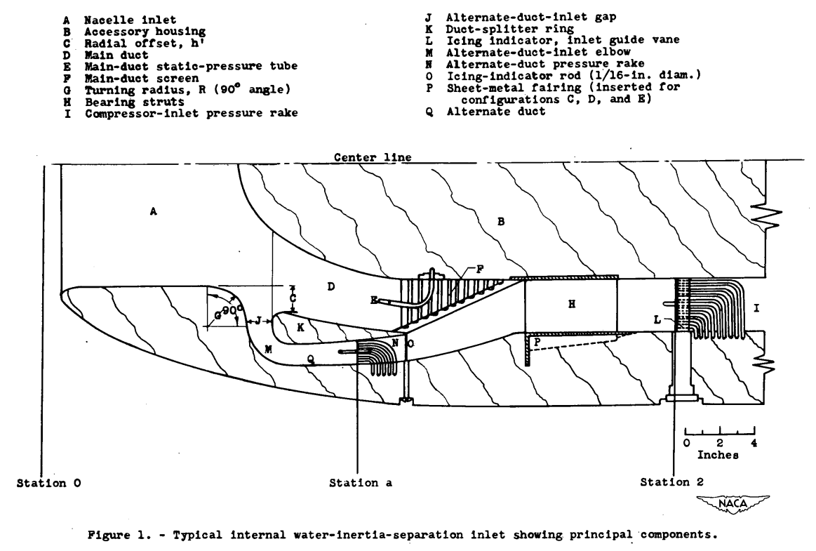
Several improved designs, based on the investigation of reference 1, were developed at the NACA Lewis laboratory; these designs were intended to operate in nonicing conditions at pressure-loss values comparable to direct-ram inlets and to give adequate ice protection with satisfactory pressure recovery through the alter-nate duct in an icing condition.
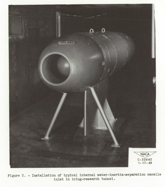
The four water-inertia-separation inlets evaluated herein were designed with the aid of a simplified analysis and the design charts presented in reference 1, whereas the inlets previously investigated were designed by a systematic variation of the configuration components prior to the development of design charts. Aerodynamic and icing studies of these four water-inertia-separation inlets reported herein were conducted in the NACA 6- by 9-foot icing-research tunnel. The data were analyzed to obtain pressure-loss values at similar mass air flows and to compare the icing tolerance that can be obtained with inertia-separation inlets with that obtained with a conventional direct-ram inlet.
RESULTS AND DISCUSSION
Aerodynamic Results
The pressure loss at various rake stations was calculated as P0-P, where the total pressure P was obtained at the required instrumented station. The integrated average total-pressure loss of all the compressor-inlet-station rakes was chosen as the configuration pressure-recovery value. The results presented were not corrected for tunnelwall interference and blocking effects. The total-pressure loss of the direct-ram inlet is used as a basis for comparison with the inertia-separation configurations investigated. The pressure loss of the various configurations is presented in terms of the mass flow per unit area measured at the compressor inlet. The effect of varying the angle of attack of the model from 0° to 6° on total-pressure loss, circumferential mass-flow variations, and velocity profiles at the compressor inlet were negligible for all inlets investigated; therefore all aerodynamic data are presented for an angle of attack of 0°.
Main-duct pressure losses. - in general, for normal nonicing operation, compressor air passed through only the main duct and the total-pressure loss for the configurations was a function of the nacelle-inlet area, the mass flow, and the area diffusion characteristics of the inlets. Only for very low mass flows did the air pass through the main and alternate ducts simultaneously for a nonicing condition; however, any effect due to flow in both ducts on the losses was negligible. The pressure loss in figure 4 is presented in terms of (P0-P2)/p0 . As shown in figure 4, the Inlets having a large nacelle-inlet area (configurations C, D, and E) 1ad a considerably lower pressure loss than the smaller nacelle-inlet-area configuration B because of the difference in dynamic pressure for similar mass flows. On a comparative basis, configurations C and D approach the pressure-loss values experienced with the direct-ram inlet (configuration A). Small changes in area at the-alternate-duct inlet did not appreciably affect the main-duct pressure-loss values, as shown by a comparison of configurations C and D. The decrease in pressure-loss values for configuration E, as compared with values for configuration B, can be mainly attributed to the decreased dynamic pressure in the nacelle inlet, which resulted in lower expansion losses at the alternate-duct inlet. in addition, the improved design of the expansion section downstream of the duct-splitter ring (fig. 3) also contributed to a reduction in pressure losses.
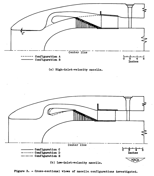
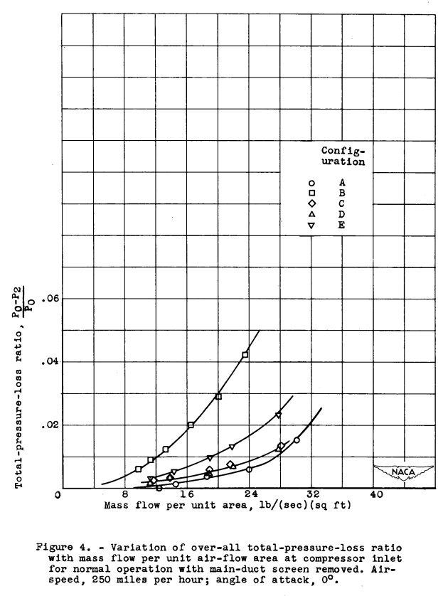
From an analysis of the static-pressure measurements obtained in the region between the duct-splitter ring and the accessory housing, it was concluded that the flow separation off the duct-splitter ring occurred at the alternate-duct inlet, especially for configuration B. The smaller degree of flow separation for configurations C and D were due to the lower duct-velocity pressure for a given mass flow and to an improved fairing-of the duct-splitter-ring leading edge. Configuration E showed a high degree of flow separation, similar to configuration B, primarily because the same duct-splitter ring was used. On the basis of the results obtained in these investigations, it appears feasible to expect a decrease in the pressure losses for configuration E by refairing the inner side of the duct-splitter ring so that a contour and area ratio similar to configurations C and D are obtained.
Alternate-duct pressure losses. - Pressure measurements made in the alternate duct with the main duct blocked by a closure plate to simulate complete blockage of the screen by ice (fig. 5) showed that, for low mass flows through the alternate duct, only a small loss in total-pressure ratio PO-Pa/PO was experienced. At higher mass flows and as the choked air-flow condition for the ducts was approached, the pressure loss increased rapidly.
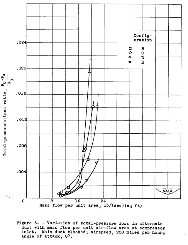
An analysis of the maximum mass flow passing through the various configurations indicates that configuration B operated at a mass flow greater than that produced by sonic velocity at the design minimum area. This condition could not exist, however, because the pressure differences available across the model were insufficient to induce sonic flow. it therefore is evident that the experimental alternate-duct-inlet gaps and areas may have varied from the design areas and gaps...
The above illustrates a some-times underappreciated aspect of testing. I have seen several test articles where as-built dimensions do not exactly match as-designed dimensions. Geometry may also distort during tests due to several factors, including loads due to installation, thermal loads, and aerodynamic loads.
If your test objects depend upon maintaining tight dimensional tolerances, you need to verify the geometry both pre-test and during test (with loads applied).
Icing Characteristics
The icing characteristics for the configurations investigated were similar, differing only as to extent and local quantity of Ice on the various engine components. Because of this similarity of icing characteristics, generalized descriptions of component icing are presented with minor differences pointed out as required. The icing photographs presented herein are typical for all inlets except where stated. The solid lines of the sketches included with some of the photographs indicate the configuration components that are seen in the icing photograph.
Typical ice formations on the nacelle-inlet lips and accessory housing, as shown in figures 11(a) and 11(c), were, very similar to those encountered in natural icing conditions (reference 6). The icing of the nacelle-inlet walls was dependent on the inlet-velocity ratios. in all cases, wall ice formations were observed at low mass-flow values that corresponded to low inlet-velocity ratios (fig. 11(b)), whereas for high mass-flow values or high inlet-velocity ratios no such wall ice formations were observed (fig. 11(c)).
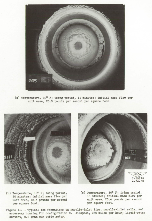
The effect of icing on the remainder of the nacelle components will be discussed in detail because the manner in which they tended to ice indicated the effectiveness of the inertia-separation inlets.
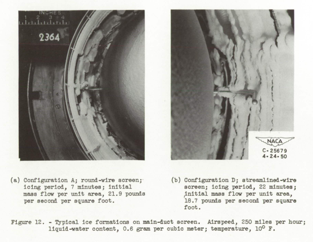
Screen icing. - in general, the icing of the round-wire screen was similar for all configurations (fig. 12(a)). M the round wires began to ice, the ice formations were parallel to the air stream; however, as the effective frontal area was reduced by the ice, the air curved around these formations and passed through the staggered rows of wires, in turn causing the ice formations to curve toward the accessory housing. Total pressure and aerodynamic forces on the ice formation sometimes became too great and the ice ridges broke off and were passed through or lodged against the screen, causing rapid and severe momentary mass-flow and total-pressure fluctuations. This rupture of the ice ridges occurred with both rime and glaze ice.
When the streamlined-wire screen with the greater wire spacing was used, the curving of the ice formations as a result of the stagger of the screen wires was even more evident. The greater collection efficiency of the streamlined wires caused a more rapid buildup of ice than the round. wires. A mushrooming tendency of the ice formations on the streamlined-wire screen is shown in figure 12(b).
Duct-splitter ring. - The ice formations on the leading edge of the duct-splitter rings (fig. 13) for the configurations investigated extended into the alternate duct to a point at which the surface of the ring was tangent to the leading-edge radius of the ring. For cases when the ice formations on the leading edge also extended into the main duct, the ice tended to project forward into the air stream along the portions that were protruding into the main duct and in time might have blocked the alternate-duct inlet.
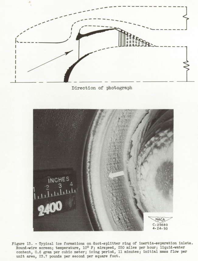
Alternate duct. - The ice formations in the alternate-duct elbow were caused by secondary inertia separation in the turn from the alternate-duct inlet to the alternate duct formed by the duct-splitter ring and the nacelle wall. Because of this effective secondary separation, however, the ridges of ice in the alternate-duct elbow built up very rapidly and choked the elbow to such an extent that the mass flow and total-pressure losses were severely affected.
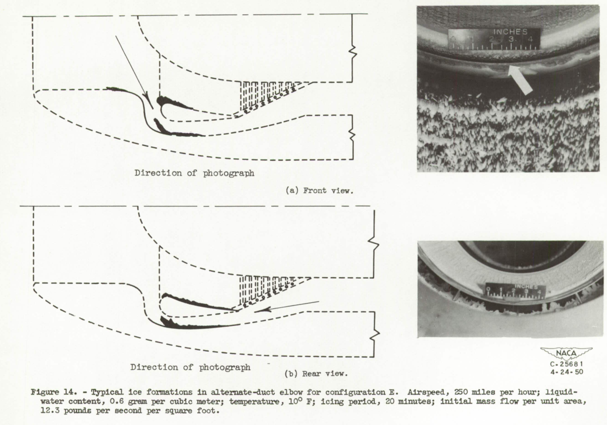
Front and rear views of a typical ice ridge in the elbow of configuration E are shown in figures 14(a) and 14(b), respectively. These ice ridges occurred approximately halfway through the elbow and protruded into the air stream, thereby reducing the effective duct area. At times, the ridges were very thin and broke off unevenly during an icing period, which caused severe fluctuations and shifts in mass flow and total-pressure losses.

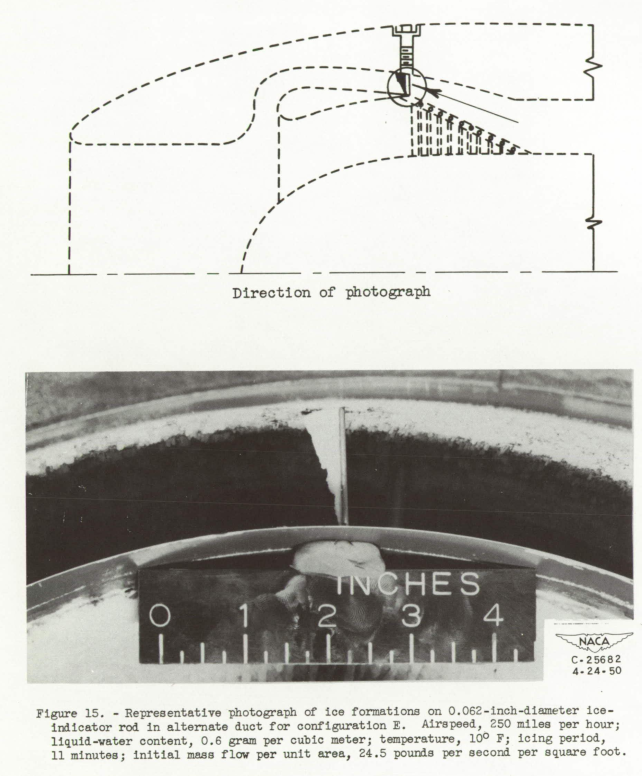
Because secondary inertia separation occurs in the alternate-duct elbow, a considerable amount of the remaining water in the incoming air is concentrated near the alternate-duct nacelle wall, as shown by the ice formation on the 0.062-inch-diameter ice-indicating rod in figure 15. The profile of the ice formation shown in figure 15 was turned approximately 90° to the air flow to facilitate photographing the ice formations.
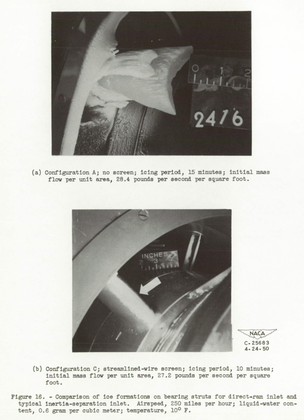
Bearing struts. - Comparative photographs of bearing-strut icing for a direct-ram inlet (no screen) and water-inertia-separation inlets are shown in figure 16. Bearing-strut icing is a minor factor with water-inertia-separation inlets (fig. 16(b)), whereas with a direct-ram inlet extremely severe icing occurs (fig. 16(a)). The heavy deposits of ice near the nacelle walls of the struts for the direct-ram inlet were caused by the deflection characteristics of the accessory housing and the ice formations on the nose of this housing.
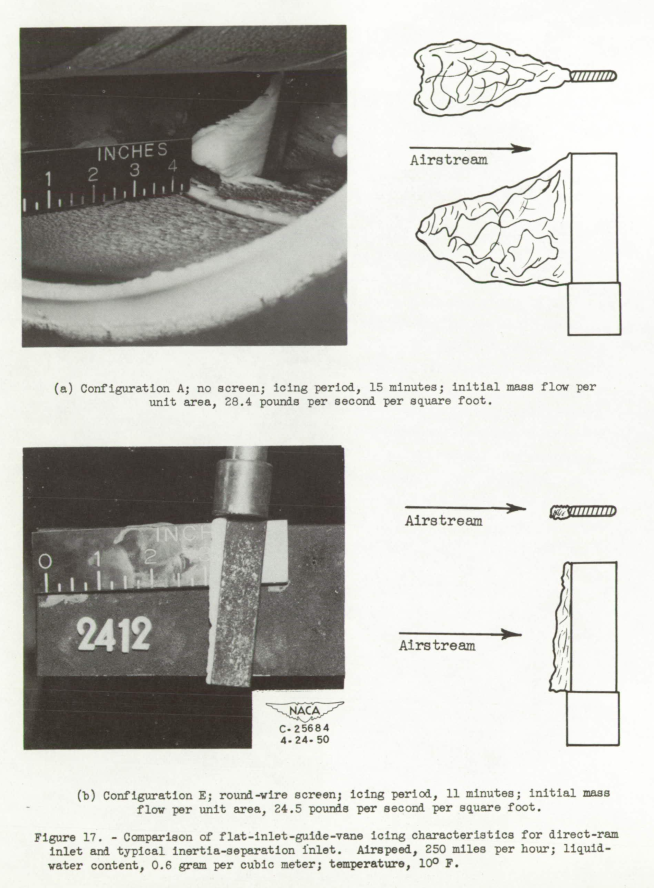
Inlet guide vanes. - With the direct-ram inlet (no screen), extremely severe ice formations on the indicator blades were observed (fig. 17(a)). The straight blades had as much as 2 inches of ice on the leading edge with a maximum frontal thickness of almost 1 inch during an icing period of 15 minutes.
Straight-indicator-blade icing characteristics are shown in figure 17(b) for a typical inertia-separation inlet. The greatest amount of ice with any configuration was approximately 0.25 inch for an icing period of 20 minutes. For most inlets, the over-all separation effectiveness was substantially similar and the differences in separation qualities were of a local nature. An examination of the magnitude of ice formations collected on the straight flat blades for configuration A (with no screen, fig. 17(a)) and configuration E (fig. 17(b)) shows that the water collection in the form of ice for the configuration P blade is approximately 8 percent of that for the direct-ram inlet. This quantity of water collection is in close agreement with calculated water- volume-intake percentage (8.4 percent) previously discussed.
The curved blade for configuration A (fig. 18(a)) was subjected to the same icing condition as the flat blade in figure 17(a).
The concave side of the curved blade was heavily iced and, based on the conventional close spacing for this size blade in an engine, the inlet guide vanes would have been completely blocked except near the accessory-housing surface.
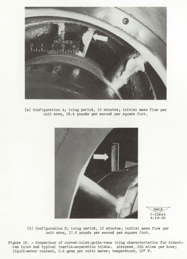
Typical curved-indicator-blade icing for inertia-separation inlets is shown in figure 18(b). Under no conditions were large deposits of ice observed on the curved blade when the inertia-separation inlets were used for icing periods up to 20 minutes, and furthermore, no noticeable mushrooming of the ice occurred at the leading edge.
Conclusions
SUMMARY OF RESULTS
From an investigation of the aerodynamic and icing characteristics of several water-inertia-separation inlets of a turbojet engine, the following results were obtained;
1. Complete icing protection for inlet guide vanes of a turbojet engine could not be achieved, as evidenced by ice formations on an ice-indicator rod in the alternate duct and on ice-indicator blades at the compressor inlet.
Comparative icing rates on ice-indicator blades for a direct-ram inlet and inertia-separation inlets showed that approximately 8 percent of the volume of water available at the nacelle inlet was not separated out of the air stream by the inertia-separation inlets investigated.
2. in a nonicing condition, the total-pressure losses of the inertia-separation inlets designed to have low dynamic pressures in the main duct approached that of a conventional direct-ram inlet. 3. Total-pressure-loss values for the alternate-duct system were considerably higher than for a direct-ram inlet. it was determined that the pressure losses for the alternate-duct system were a function of duct Mach number and duct-diffuser characteristics. Severe pressure losses occurred when the duct Mach number exceeded values in the range of 0.5 to 0.6.
4. No significant effects on total-pressure losses, velocity profiles at the compressor inlet, or circumferential mass-flow shifts for the inlets investigated were observed for angles of attack up to 6.
5. Secondary water inertia separation in the alternate duct caused heavy duct-elbow icing and resulted in a decreasing mass flow and rapid total-pressure losses, although the use of inertia-separation inlets increased the time required to reach a particular loss in pressure or mass flow by a factor of approximately 4 compared with the time required by the direct-rain inlet with compressor-inlet screen under the same conditions.
6. A mass-flow analysis of all configurations showed that only the configuration with the largest alternate-duct inlet gap (1.9 in.) could pass a mass flow through the alternate duct that is required by current engines. This air flow, however, could only be passed through the duct at the choking Mach number with attendant high total-pressure losses. Large mass flows at Mach numbers below 1.0 at the minimum area in the alternate duct, resulting in lower total-pressure losses, may be obtained by increasing the diameter of the nacelle in order to obtain a larger alternate-duct area.
Citations
NACA-RM-E50E03 is cited once times, per scholar.google.com.
The citation is from
- von Glahn, Uwe H., Callaghan, Edmund E., and Gray, Vernon H.: NACA Investigations of Icing-Protection Systems for Turbojet-Engine Installations. NACA-RM-E51B12, 1951. ntrs.nasa.gov
Related
This is part of the Engine Inlet Icing Thread.
Notes
-
von Glahn, Uwe H., and Blatz, Robert E.: Investigation of Aerodynamic and Icing Characteristics of Water-Inertia-Separation inlets for Turbojet Engines. NACA-RM-E50E03 ntrs.nasa.gov, 1950. ↩