"rain deflection by jet blast appears feasible for flight speeds"
"Preliminary Data on Rain Deflection from Aircraft Windshields by Means of High Velocity Jet-Air Blast" 1
Abstract
A preliminary experimental investigation is being conducted to determine the feasibility of preventing rain from impinging on aircraft windshields by means of high-velocity jet-air blast.
The results indicate that rain deflection by jet blast appears feasible for flight speeds comparable with landing and take-off speeds of interceptor-type jet aircraft; however, attainment of good visibility through the mist generated by raindrop breakup presents a problem. For the simulated windshield and the lower windshield angles used in the investigation, air-flow rates of the order of 3.3 pounds per minute of unheated air per inch of windshield span were required for adequate rain deflection at a free-stream velocity of 135 miles per hour.
A method has been devised whereby it is possible to produce large-diameter water drops (1000 to 1500 μ) in a moving air stream, without breakup, at speeds in excess of 175 miles per hour.
Discussion
Windshield rain removal is often designed in the same group as ice protection. A design group I worked in was named "Ice and Rain Protection". SAE AIR-1168/4 is titled “Ice, Frost, and Rain Protection” [SAE Aerospace Applied Thermodynamics Manual, 1969 (regularly updated, currently document sae.org)]
That was historically where the knowledge of water drops, air flow control, and mechanical systems resided.
So, it is not surprising that a rain-removal publication is in the "Selected Bibliography of NACA-NASA Aircraft Icing Publications".
For brevity, only some results with the 60° air jet discharge angle will be illustrated here.
INTRODUCTION
Obtaining good removal of water from airplane windshields for better visibility during flight through rain is becoming an increasingly important problem In regard to flight safety. The need for good rain removal is especially acute during airplane descent and landing. The high landing speeds of modern interceptor-type airplanes is probably the major single factor contributing to the need for better rain removal systems. However, in some cases, the design of an airplane and its pilot enclosure is such that during landing, even under good weather conditions, the forward field of vision is limited to such an extent that any further decrease in visibility could be detrimental to flight safety. Pilot reports indicate that, when making runway landings in rain with present operational interceptor-type aircraft having an inadequate or no rain removal system, many pilots make their observations almost entirely through the side panels because of extremely bad forward visibility.
Because of the growing seriousness of the problem, the NACA Lewis laboratory is conducting a preliminary investigation to study the possibilities of preventing rain from impinging on aircraft windshields at flight speeds comparable with landing and take-off speeds of jet aircraft. The system being investigated is one wherein raindrops are broken up by means of a high-velocity air blast and the resulting mist is deflected around the windshield without impingement. Such a system has several inherent advantages. Air jets employed may be mounted flush to the fuselage or easily streamlined and thus would not penalize the airplane aerodynamically for high-speed flight. The high air-handling capacities of present jet engines, together with the high pressures and temperatures available, add to the desirability for using such a system. Thrust losses due to bleeding the compressor for air used to deflect the raindrops are in most cases so small (less than 1/2 percent) as to be negligible, even for take-off. A system of this type employing heated air and capable of providing adequate rain removal (or deflection) could probably serve also as an excellent windshield anti-icing system.
The present study is being conducted in the 2- by 20-Inch tunnel at the NACA Lewis laboratory. Because the investigation is still preliminary in scope, the experimental study is restricted almost entirely to the mechanics of water-drop breakup by high-velocity jet-air blast and to the determination of the over-all feasibility of such a system. Thus far, all work has been done with unheated air jets operating in choked flow and discharging from straight circular tubes.
APPARATUS AND PROCEDURE
A schematic drawing of the tunnel test section with simulated wind-shield, raindrop discharge nozzle, and air-jet discharge tubes installed is shown in figure 1. The water discharge nozzle, which provides a single stream of drops, is located just upstream of the beginning of the test section. Air jets discharge through straight circular tubes posi- tioned at various distances. forward of the windshield and directed at various angles to the main air stream.
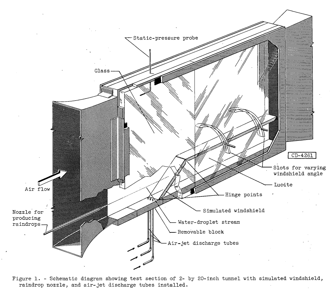
The simulated windshield, made of Lucite, is 2 inches wide and 12 inches long along the slant face. An afterbody is provided to better simulate a windshield-canopy combination. The windshield angle may be varied from 25° to 90° by means of hinges incorporated in the windshield design and slots provided in the Lucite portion of the test-section wall (see fig. 1). With the exception of the Lucite portion, the test-section walls are optically flat glass installed to enable photographing by means of schlieren apparatus. The schlieren apparatus consists of a single mirror system of conventional design but incorporating a micro-second flash arrangement. Air-jet discharge tubes are positioned to discharge at angles of 30°, 45°, 60°, and 90° to the main air stream and to intersect the plane of the tunnel floor (removable block) at a surface distance of 3/4 inch ahead of the windshield leading edge. In addition to the 3/4-inch location, jets discharging at the 90 angle may be positioned at a distance of 2 and 4 inches ahead of the windshield. For that portion of the investigation which included the simulated windshield, the vertical distance from tunnel floor to the open end of the discharge tubes ranged from 1/2 to 3/4 inch.
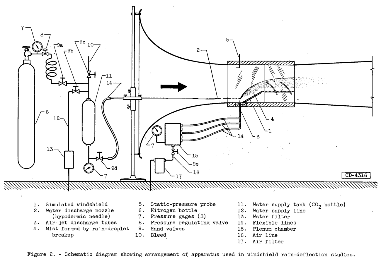
Because the raindrop nozzle was designed to operate at high water discharge velocities and pressures, it was necessary to provide a high-pressure supply system capable of handling working pressures of the order of 1000 pounds per square inch maximum. A schematic diagram of the water supply system together with an over-all sketch of the test arrangement is shown in figure 2.
RESULTS AND DISCUSSION
In flight through rain, essentially all the raindrops directly ahead of the airplane windshield will come on to strike the windshield even at the lower landing speeds. Because these raindrops are large in diameter and mass, and consequently possess great inertia, they cannot follow the air streamlines around the windshield but go on to strike the windshield surface and thus obscure vision. However, if these large raindrops can be broken up into very fine, water droplets somewhere ahead of the windshield, then the resulting fine droplets will follow the air streamlines approximately and flow around the windshield without impingement. One method for achieving raindrop breakup is by means of a series of high-velocity air jets located some nominal distance (in.) ahead of the windshield.
In order to study this raindrop disintegration by jet blast, it was first necessary to produce raindrops at tunnel air velocities of about 150 miles per hour. Unless special precautions are taken, however, water drops of raindrop size break up when subjected to the accelerations necessary to bring their velocity up to tunnel air speed. Therefore, the first phase of the investigation was conducted for the purpose of devising a means for producing water drops of raindrop size in a wind tunnel and at speeds comparable with landing and take-off speeds of jet airplanes.
...
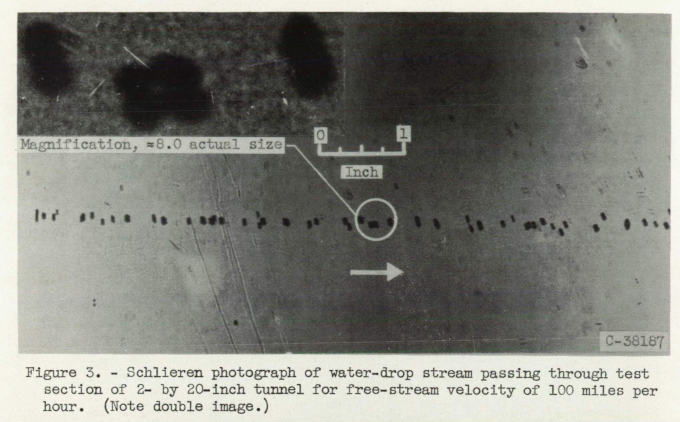
An example of the size and number of drops produced by this system is presented in figure 3. The photograph shows the narrow band of water drops passing through the tunnel test section for a free-stream velocity of 100 miles per hour. The simulated windshield and air jets were not present in the test section at the time the picture was taken. The drops are essentially spherical in shape, but visual studies with strobo-scopic light give evidence that the drops are undergoing distortions due to aerodynamic forces or surface tension as the drop seeks to establish a true spherical shape. The photograph shown was taken at the upstream end of the test section (about 8 to 12 in. from the hypodermic needle), but the drops travel through the entire length of test section (3 ft) without further change. The photograph was taken by means of a single-mirror schlieren apparatus which provides results having a double image as noted in the figure. The image displacement takes place in a plane almost perpendicular to the line of droplet travel.
Rain Deflection by Jet Blast
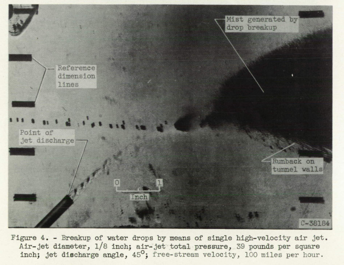
The single stream of drops presented in figure 3 provides a means for studying raindrop - air-jet interaction (fig. 4). The photograph shows a stream of drops being torn apart by means of a high-velocity air jet discharging from a straight tube having a 1/8-inch inside diameter. The air jet is discharging at an angle of 45° to the air stream and at an exit total pressure of 39 pounds per square inch (bench tests were conducted to determine pressure losses through the air supply system). The free-stream velocity is 100 miles per hour, and the drops are passing through the test section at a vertical distance of about 1 7 inches above the point of air-jet discharge or approximately 2 inches above the tunnel floor. The photograph shows that rapid and rather complete breakup of drops is achieved by means of the high-velocity air jet. The dark area downstream of the point of air-jet - raindrop interaction represents the dense mist containing the many fine droplets created by raindrop breakup.
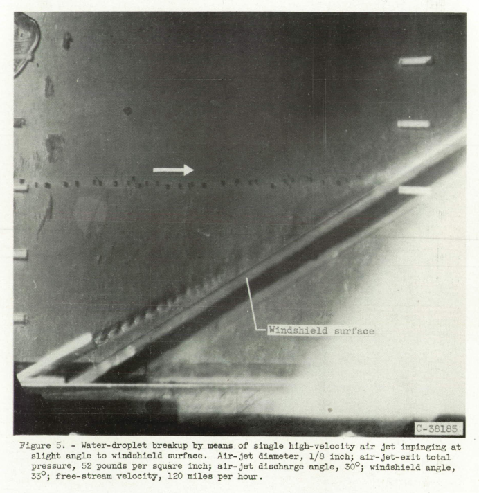
Initial tests with the simulated windshield were made with jets discharging almost parallel to the windshield to determine the amount of raindrop breakup and windshield scrubbing action achieved. A photograph showing a single 1/8-inch-diameter air jet impinging at a slight angle on the windshield is presented in figure 5 for a free-stream velocity of 120 miles per hour. The air-jet-exit total pressure is 52 pounds per square inch, the jet discharge angle is 30°, and the windshield angle is 33°. Oncoming drops are broken up just before they contact the windshield surface, but the point of breakup is so close that the resulting spray goes on to strike the windshield. With this arrangement, a great portion of all the water ahead of the windshield comes on to strike the windshield in the form of mist.
Because unheated air was used throughout the investigation, the figure shows that mechanical action of the jets alone will not provide rain removal adequate for good visibility for the case where cold-air jets impinge on the windshield. Such a system would have to rely heavily on evaporation of the mist by hot-air jets to provide good visibility. Whether the necessary rapid evaporation can be obtained with hot-air jets is a subject for future study.
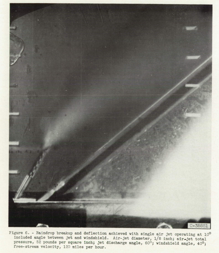
Increasing the angle between the air jets and the windshield (fig. 6) results in better and more complete breakup of the raindrops. The mist now has been lifted vertically and moved further away from the windshield so that much of the spray misses the windshield entirely. Conditions for figure 6 are as follows: free-stream velocity, 120 miles per hour; air-jet diameter, 1/8 inch; jet pressure, 52 pounds per square inch; jet discharge angle, 60°; windshield angle, 40°.

Conclusions
The results obtained thus far in a preliminary investigation to determine the feasibility of an aircraft-windshield rain-deflection system using jet-air blasts indicate that
1. Rain deflection by jet blast appears feasible for flight speeds up to at least 150 miles per hour for low-angle windshields (35° or less); however, visibility through the mist generated by raindrop breakup presents a problem.
2. For the simulated windshield used, air-flow rates of the order of 3.3 pounds per minute of unheated air per Inch of windshield span were required for adequate rain deflection at a free-stream velocity of 135 miles per hour. The air-flow rate is equivalent to that obtained with three 1/4-inch-diameter jets equally spaced across the 2-inch span of windshield (32° windshield angle) and operating at 35-pound-per- square-inch exit total pressure.
Air-jet rain removal is used today on some aircraft. Wipers are more commonly used. Rain-repellent fluid sprays are also used, usually as a supplement for wipers.
Citations
One citation for NACA-RM-E55E17a was found at scholar.google.com.
The citation was
- Selected Bibliography of NACA-NASA Aircraft Icing Publications, NASA-TM-81651, August, 1981. ntrs.nasa.gov
NACA-RM-E55E17a does not cite any publications. Author Ruggeri (and frequent coauthor Callaghan) on prior publications had carefully noted citations and precedents. This implies that NACA-RM-E55E17a originates the concept of air-jet rain removal.
Having only one citation definitely marks NACA-RM-E55E17a as an under-appreciated publication, a "lost gem" of the NACA-era.
Related
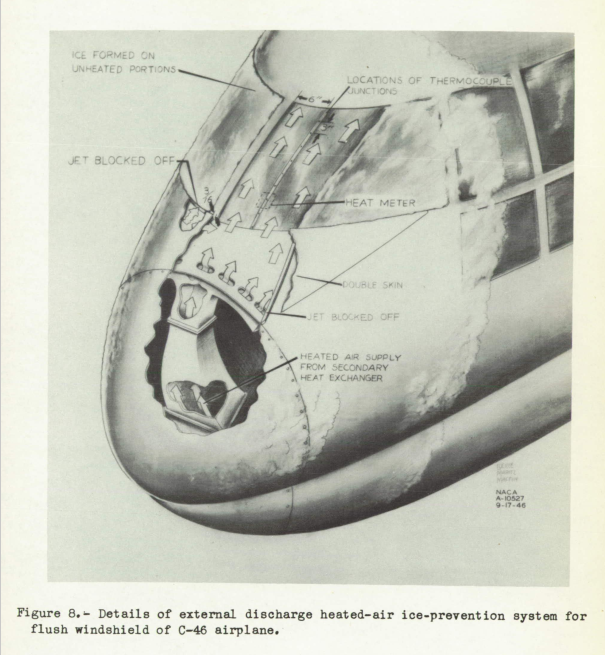
See also Windshield ice Protection, where in NACA-TN-1434 an air jet ice protection system is discussed:
Notes
-
Ruggeri, Robert S.: Preliminary Data on Rain Deflection from Aircraft Windshields by Means of High Velocity Jet-Air Blast. NACA-RM-E55E17a, July 25, 1955. ntrs.nasa.gov ↩