"For practical application ... the discharging of heated jets into an air stream requires knowledge of the temperature profiles downstream of the heated jet and of the depth of penetration"
"General Correlation of Temperature Profiles Downstream of Heated Air Jet Directed at Various Angles to Airstream" 1
Abstract
An experimental investigation was conducted to determine the temperature profiles downstream of heated air jets directed at angles of 90°, 60°, 45°, and 30° to an air stream. The profiles were determined at two positions downstream of the jet as a function of jet diameter, jet density, jet velocity, free-stream density, free-stream velocity, jet total temperature, orifice flow coefficient, and jet angle. A method is presented which yields a good approximation of the temperature profile in terms of the flow and geometric conditions.
Discussion
INTRODUCTION
The discharging of heated high-velocity jets of air or vapor into an air stream is employed in many installations either as a means of heating the air stream or as a method of disposing of hot discharge gases; For practical application, however, the discharging of heated jets into an air stream requires knowledge of the temperature profiles downstream of the heated jet and of the depth of penetration of the jet into the air stream.
Heating an air stream by means of heated air jets directed perpendicularly to the air stream has been previously reported in references 1 and 2. A method is presented in reference 1 by which the temperature profile and the depth of penetration of a circular heated air jet directed perpendicularly to the air stream may be predicted at any point downstream of the jet.
Because many installations employ jets which are directed at an angle other than 90° to the airstream, a study of the temperature profiles downstream of circular heated air jets directed at various angles to the air stream was conducted in the 2- by 20-inch tunnel at the NACA Lewis laboratory. Sixteen heated air jets were investigated for a range of free-stream velocities, jet total temperatures, jet total pressures, and jet angles. The 16 jets investigated comprised a group of basic jets with four diameters and each diameter was investigated for four jet angles.
APPARATUS AND PROCEDURE
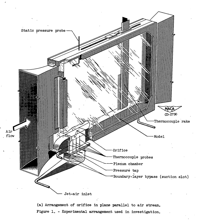
A sketch showing the experimental arrangement used in the investigation to determine the temperature profile downstream of a heated air jet issuing at various angles to an air stream is shown in figure 1(a). Heated air for the jets was obtained by passing high-pressure air through electric heaters and into a plenum chamber, the upper portion of which contained the orifice blocks. The rate of jet-air flow was measured by means of calibrated orifices located upstream of the electric heaters. Each of the 16 jet orifices was investigated for a range of jet pressure ratios (ratio of jet total pressure measured at exit to outlet static pressure) from 1.2 to 3.5. The jet total pressure was measured by means of a pressure tap located in the wall of the plenum chamber and was corrected for total pressure loss through the flow passages. (Bench tests were conducted to determine the pressure loss through the passages under choked-flow condition In still air.) The jet total temperatures and free-stream velocities investigated were nearly constant values of 660° and 860° F, and 235 and 400 feet per second, respectively. The temperature profiles were measured by means of a movable thermocouple rake which consisted of 33 thermocouple probes spaced 0.250 inch apart. The thermocouple rake was inserted at positions 6.47 and 18.0 inches downstream of the discharge-orifice center.
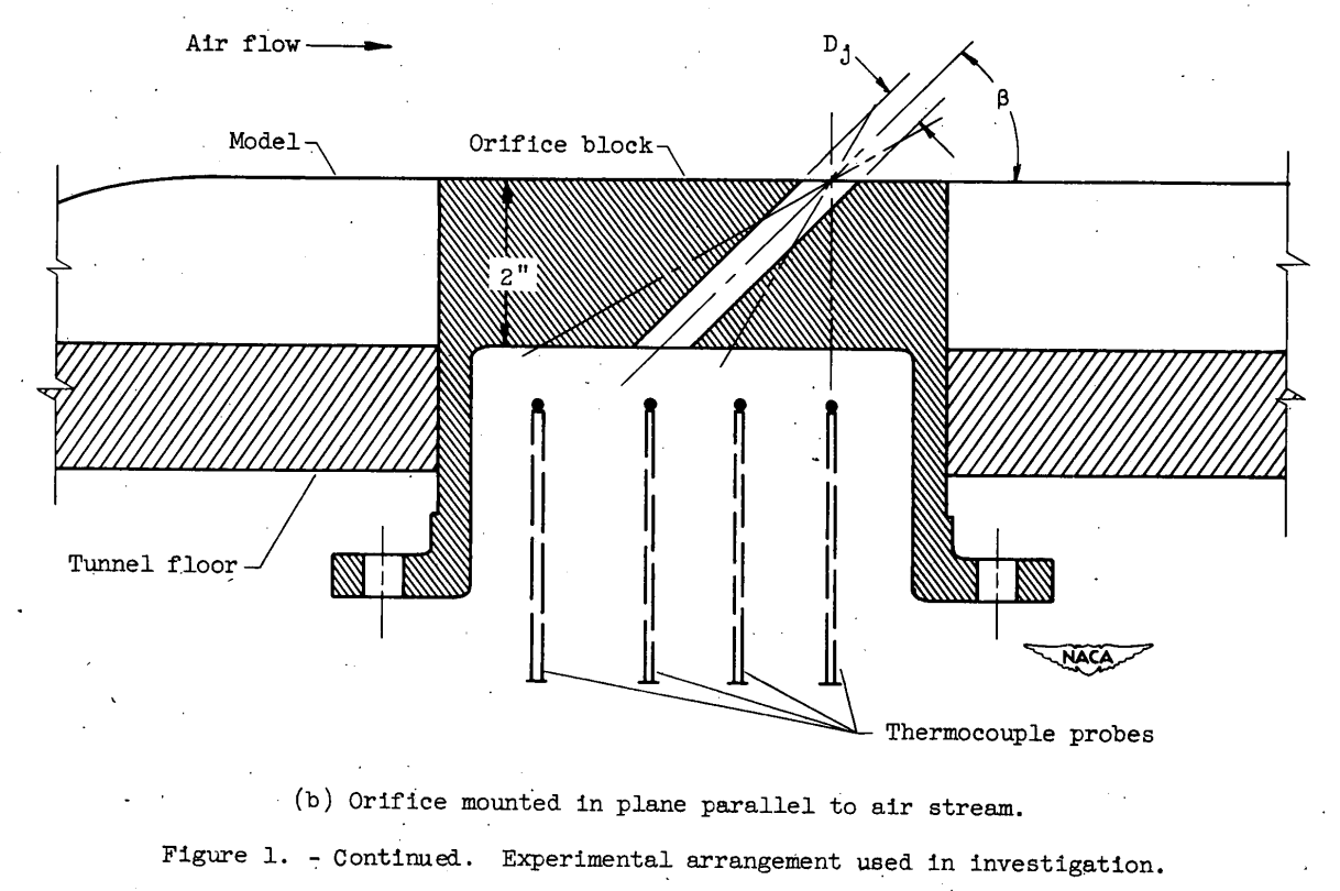
The orifices used in the investigation consisted of smooth circular holes machined in cast Inconel orifice blocks as shown in figure 1(b). The orifice holes were 0.250, 0.375, 0.500, and 0.625 inch in diameter and each orifice was investigated at jet angles of 90°, 60°, 45°, and 30° to the air stream. Although the holes are circular in cross section, the plan form of the orifices (jet exit) is elliptical in a plane parallel to the main stream except for the cases where the jet angle 3 is 90°. The orifice blocks were so machined that the center line of the 16 orifices investigated passed through the same point at the surface of the model. The length of the passage through the various orifice blocks varied in length from 2.0 inches for jets issuing at 90° to the air stream to 4.0 inches for the jets discharging at 30° to the main tunnel flow. The term "orifice diameter" or "jet diameter" is used throughout this report when referring to the diameter of the discharge opening measured perpendicular to the jet axis (fig. 1(b)).
The tunnel boundary layer was removed by suction upstream of the orifices to minimize tunnel wall boundary-layer effects (see fig. 1).
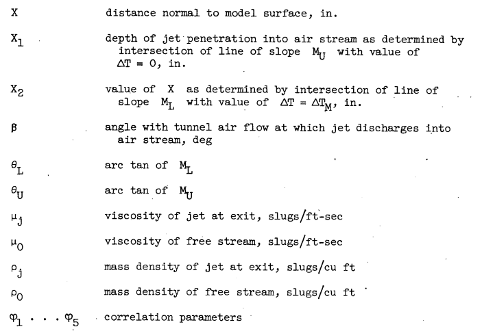
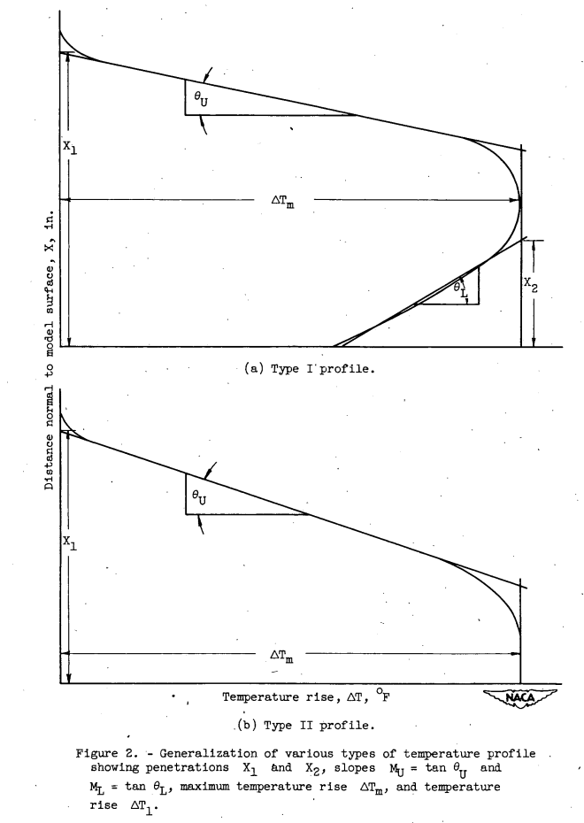
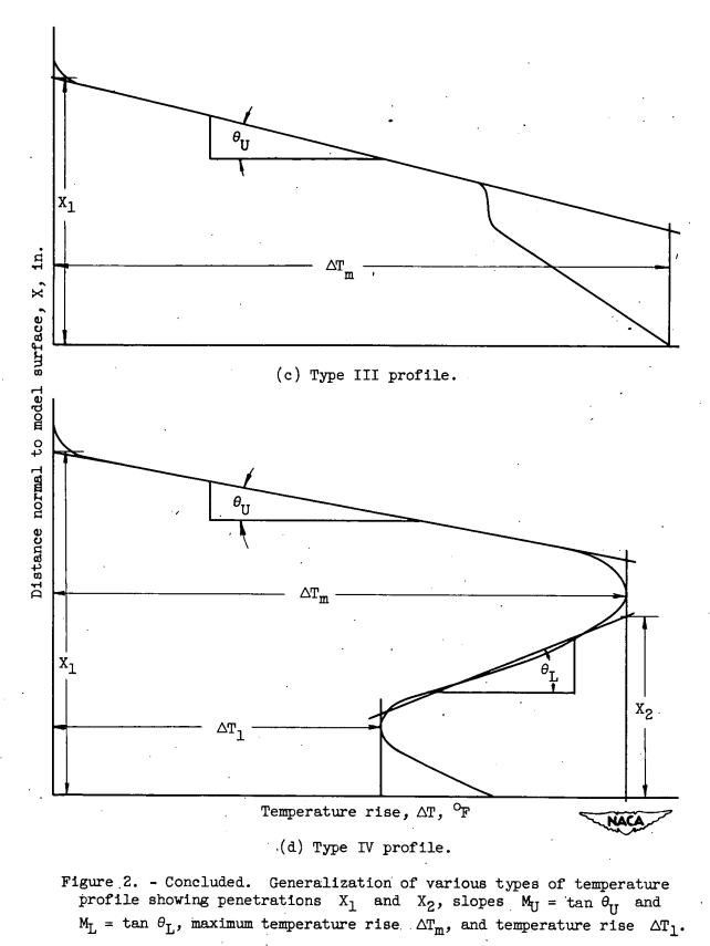
In a study of the data for jets issuing at angles of 60°, 45°, and 30° to the air stream, it was found that in most instances, the general shape of the temperature profiles differed greatly from that obtained for a jet discharging at an angle of 90° (fig. 2(a)). However, the study also showed that these various types at profile had certain consistent characteristics similar to those noted for a jet discharging at 900 to the air stream. It was found that four basic types of temperature profile, measured downstream of the jets, could be used to represent the profile data for all jet diameters and jet angles investigated (fig. 2). Also shown in figure 2 is the manner in which these profiles are approximated by straight lines.
RESULTS MID DISCUSSION
Flow Coefficient
The discharge-orifice flow coefficient C is defined as the ratio of the actual measured mass flow to-the theoretical mass flow. The actual mass flow through the various discharge orifices was measured by means of calibrated measuring orifices located upstream of the electric heaters. The theoretical mass flow was calculated from the compressible flow relations based on conditions at the jet exit. (Bench tests were made to determine the pressure loss through the jet flow passages under choked flow conditions.) The total-temperature loss through the jet flow passages was found to have a negligible effect on the flow coefficient (less than 0.5 percent). As expected, the measured flow coefficient for all the jets investigated was found to be independent of jet pressure ratio at values greater than choking. The flow coefficient ranged from 0.88 to 0.92 for all jets investigated and the arithmetic average was 0.90. Because the measured flow coefficients obtained for the orifices used in this investigation may not be applicable for other installations, no data for the flOw coefficients are presented in this report.
Correlation of Penetration Coefficient X1 C^0.5 Dj
...
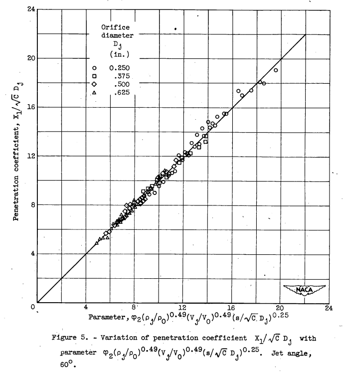
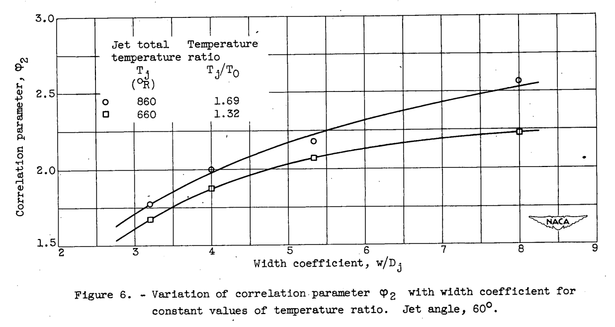
The over-all parameter obtained for correlation of the penetration coefficient X1 C^0.5 Dj for a jet issuing at 60° to the air stream was found to be φ2 (ρj/ρo)^0.49 (Vj/Vo)^0.49 (s C^0.5 Dj)^0.25 . The linear variation of the penetration coefficient with this parameter is shown in figure 5 for all values of orifice-diameter, mixing distances, free-stream velocities, and temperature ratios investigated. The density-ratio exponent, the velocity-ratio exponent; and the ratio of mixing distance to effective diameter exponent were found to remain constant for all orifice diameters or width coefficients investigated. The variation of the correlation parameter 2 with width coefficient w/Dj is shown in figure 6 for constant values of temperature ratio.
Comparison of Calculated and Experimental Profiles
The correlation of the various coefficients 'with the flow and geometric parameters presented in the foregoing discussion provides a method by which an approximation of the temperature profile downstream of a heated-air jet directed at an angle to the air stream may be obtained.
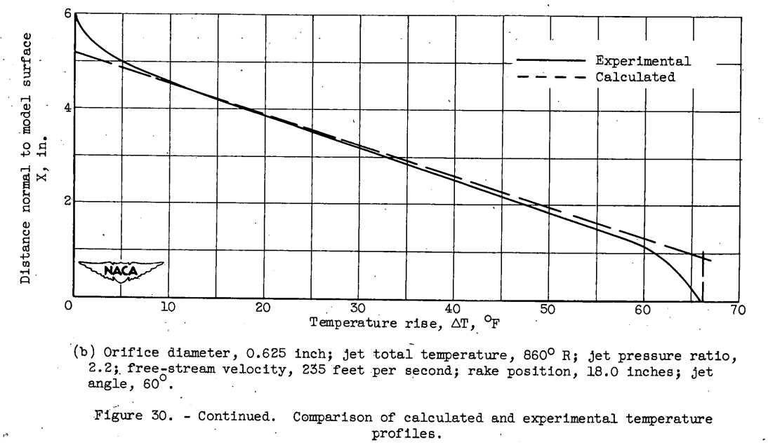
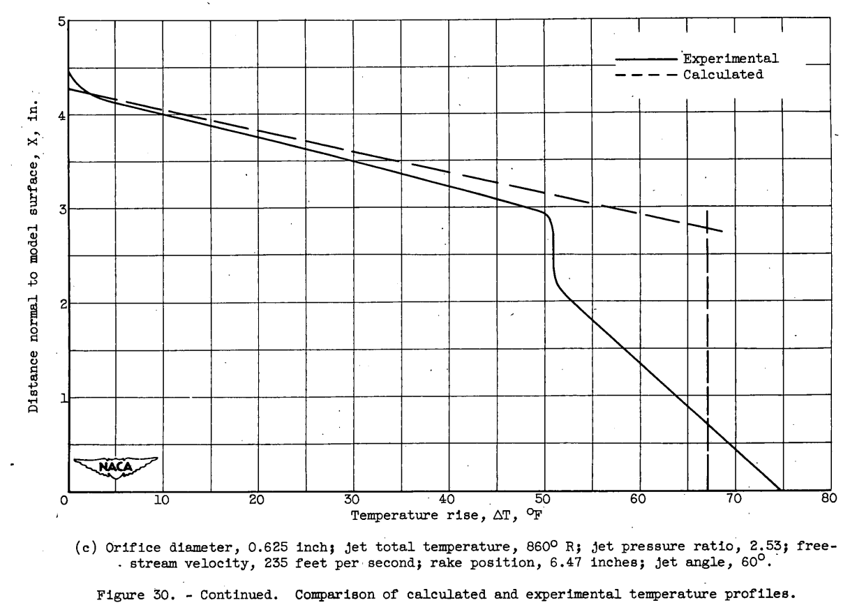
Based on the experimental conditions, a number of profiles were calculated and compared with the actual profiles. Some typical - examples are shown in figure 30. A study of this figure shows that, in general, the approximate solution is in good agreement with the experimental data and provides a reasonably simple method for obtaining the temperature profile downstream of a heated-air jet directed at an angle to the air stream.

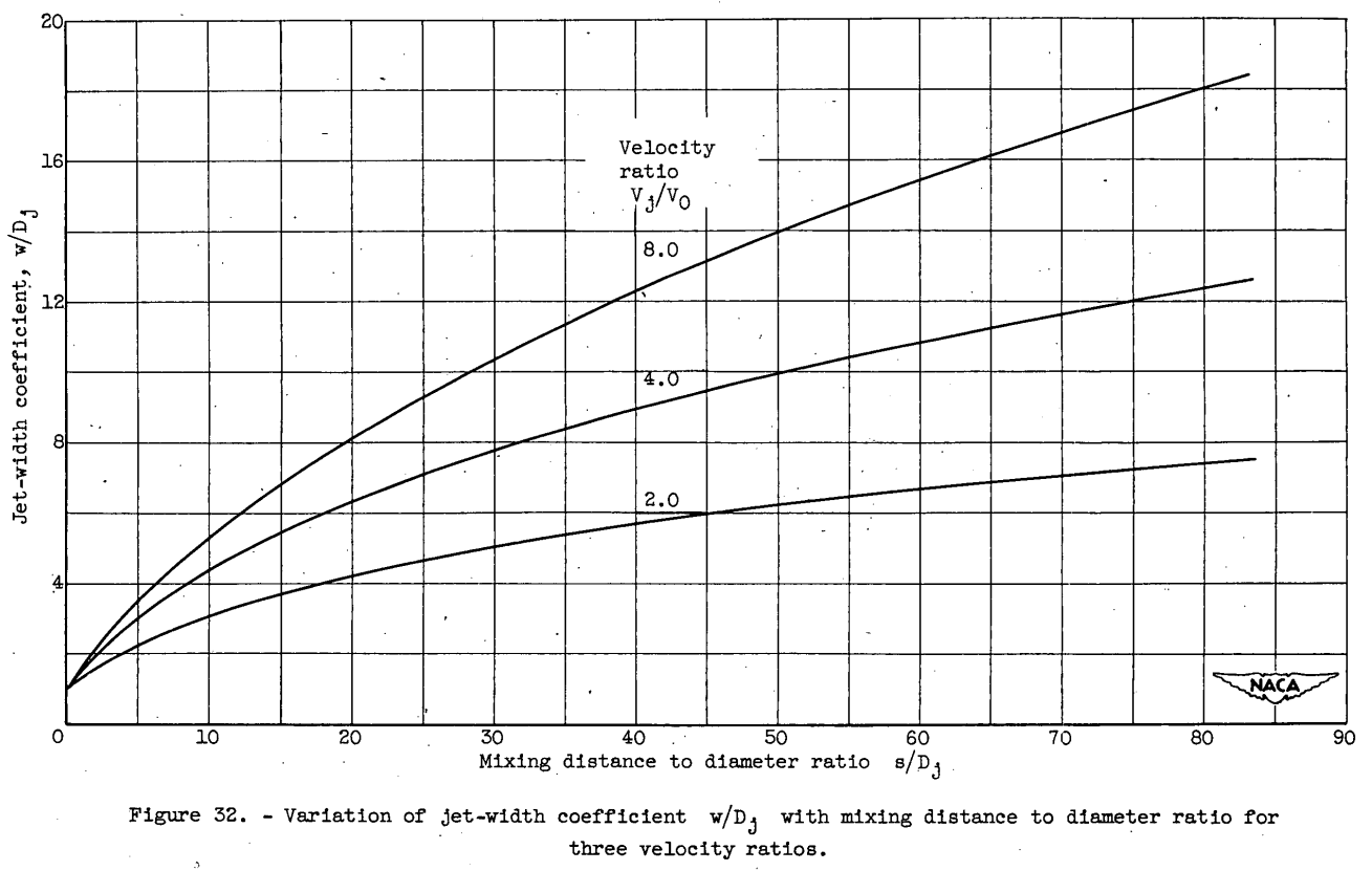
efore calculating the various parameters needed for obtaining the temperature profiles, it is necessary to first determine the proper jet-width coefficient at the mixing distance in question. If, for the problem being considered, the jet is discharging into an unbounded air stream, the jet is unrestricted, and the width coefficient has but one possible value for a given s/D (fig. 32). If the jet being considered is discharging into a duct, the proper width coefficient to use in calculations is dependent on whether or not the jet is restricted. If the jet-width coefficient as determined from figure 32 is greater than the duct-width coefficient, the jet is restricted in its expansion and the duct-width coefficient is the important parameter. If the jet-width coefficient is less than the duct-width coefficient, the jet is relatively unrestricted and the jet-width coefficient becomes the important parameter and should be used in the calculations.
COMPARISON OF CALCULATED MID EXPERIMENTAL JET BOUTIDARIES
During the course of the investigation, numerous photographs of the jet boundary were made by means of the Schlieren technique and the results were compared with the calculated jet boundary obtained by use of the correlation curves presented herein. For illustrative purposes, the calculated boundaries were obtained from both a constant value of width coefficient based on tunnel dimensions and a variable jet-width coefficient based on the actual width of the jet at the point of interest (fig. 32).
Some typical examples of the comparisons obtained are shown in figure 33 for the four jet angles investigated. The distance normal to the model surface is shown plotted against the mixing distance. A study of this figure shows that use of the width coefficient based on the actual jet width yields calculated profiles which are in reasonably good agreement with the measured profile obtained from Schlieren photographs. The use of a constant width coefficient, based on tunnel dimensions, yields calculated profiles which deviate considerably from the actual profile for small values of mixing distance where the jet is not confined by the tunnel walls. The value of mixing distance at which the two calculated curves become one curve is the point beyond which the jet becomes confined by the walls of the tunnel.
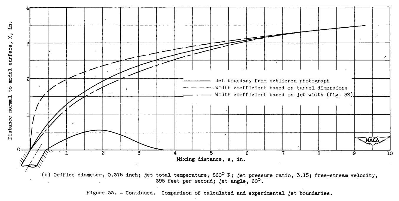
A study of the Schlieren photographs also shows that the lower jet boundary leaves the surface of the model before sufficient expansion and mixing of the jet with the air stream takes place to enable the jet to contact the surface. The surface distance downstream of the orifice which is unheated by the jet increases with decreasing jet angle for the range of jet angle investigated.
Conclusions
A method which provides a reasonably simple means of obtaining the approximate temperature profile downstream of a heated-air jet directed at an angle to the air stream has been presented in terms of dimensionless parameters of the flow and geometric conditions.
Citations
NACA-TN-2855 is cited 25 times, per scholar.google.com.
Notes
-
Ruggeri, Robert S.: General Correlation of Temperature Profiles Downstream of Heated Air Jet Directed at Various Angles to Airstream. NACA-TN-2855, 1952. ntrs.nasa.gov ↩