"Excellent correlation was obtained between the results for a jet discharging into still air and ... into a moving air stream"
"Investigation of Flow Coefficient of Circular, Square, and Elliptical Orifices at High Pressure Ratios" 1
Abstract
An experimental investigation has been conducted to determine the orifice coefficient of a jet directed perpendicularly to an air stream as a function of pressure ratio and jet Reynolds number for circular, square, and elliptical orifices. The effect of air-stream velocity on the jet flow was also determined for three tunnel-air velocities. Equations for the flow coefficients In terms of jet Reynolds number and pressure ratio were obtained for the various shapes. Excellent correlation was obtained between the results for a jet discharging into still air and the results for a jet discharging into a moving air stream, provided that the correct outlet pressure was used.
Discussion
INTRODUCTION The introduction of a gas or a vapor into an air stream for purposes of heating or cooling the air stream may be easily accomplished by the use of a high-velocity jet directed perpendicularly to the air stream, as reported in reference 1. In order to evaluate the heating or cooling effect of such a jet, knowledge of the mass air flow of the jet or, more fundamentally, the discharge coefficient of the orifice from which the jet is issuing is essential. In addition to the effects of jet Reynolds number and orifice shape on the discharge coefficient, the jet pressure ratio and the interaction of the air stream and the jet must be considered.
An investigation to determine the orifice-discharge coefficient of a high-velocity air jet directed perpendicularly to an air stream was undertaken in a 2- by 20-inch duct tunnel at the NACA Lewis laboratory. The discharge coefficients of circular, square, and elliptical orifices were determined at tunnel-air velocities of 160, 275, and 380 feet per second for several jet (orifice) areas, a range of pressure ratios from 1.15 to 3.2, and a jet total temperature of approximately 400 F.
Flow coefficients in still air
The nine 1/16-inch-thick of three circles, two thin-plate orifices investigate ellipses with an axis ratio of 4:1 1 two ellipses with an axis ratio of 2:1, and two squares. The circular orifices had diameters of 0.375, 0.500, and 0.625 inch;, the ellipses and squares had areas equivalent to the 0.375- and 0.625-inch-diameter circles. Each orifice was investigated over a range of pressure ratios from 1.15 to 3.2 and for jet total temperatures of approximately 70 0 and 4000 F. Air for the jets was obtained by passing high-pressure air through an electric heater and into a plenum chamber, the upper wall of which contained the orifice, as shown in figure 1. The mass flow was measured by a calibrated orifice in the ducting upstream of the heater. The calibration curve for the measuring orifice indicated an over-all accuracy of 2 percent.
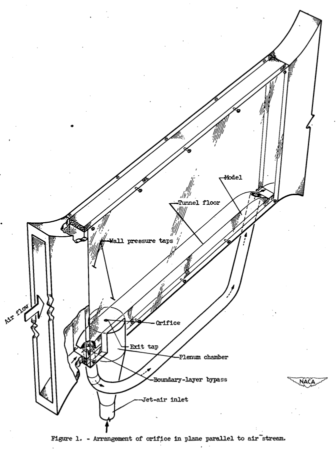
The plenum chamber was constructed with an inside diameter of 6 inches to minimize the effect of approach velocity and to insure that the static temperature and pressure measured in the plenum chamber would be equal to the total temperature and pressure of the jet at the vena contracta.
Static pressures were measured at the orifice and at a point upstream of the orifice by pressure taps in the tunnel walls.
RESULTS AND DISCUSSION
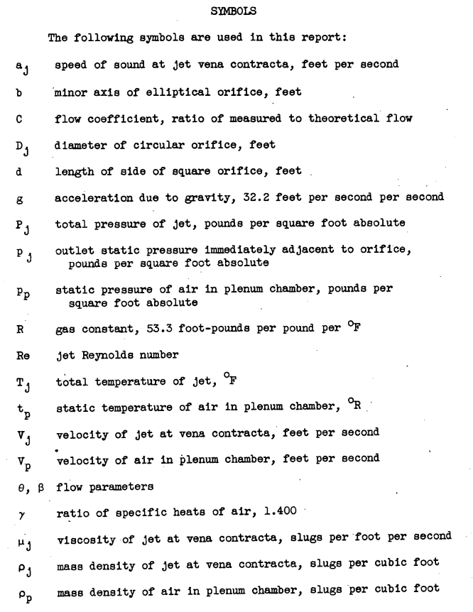
A cross plot of all the circular-orifice data is shown in figure 4 where the flow coefficient is plotted as a function of jet Reynolds number ρj Vj Dj / μj for constant Values of pressure ratio. The curves obtained are similar to those normally given for orifice-discharge coefficients at pressure ratios near 1. The flow coefficient decreased with increasing jet Reynolds number.
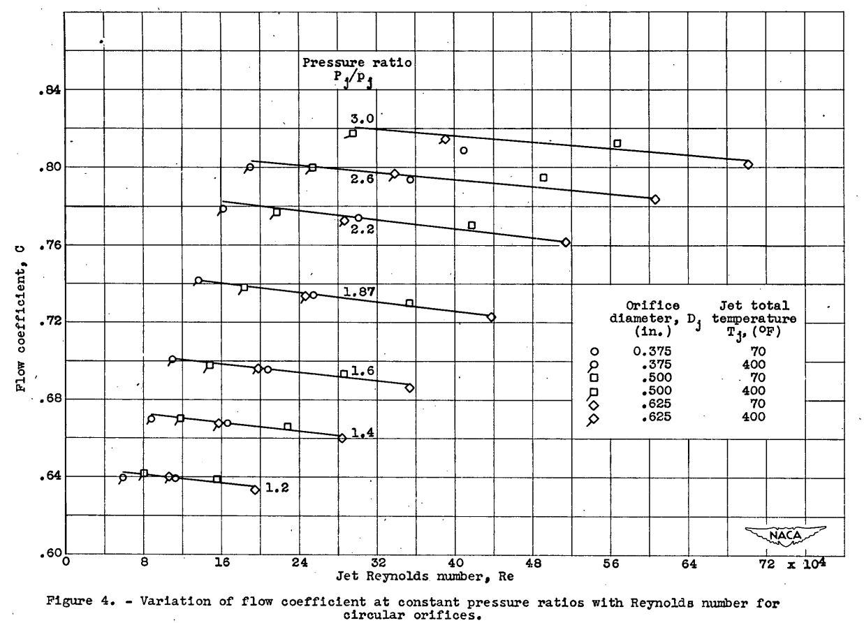
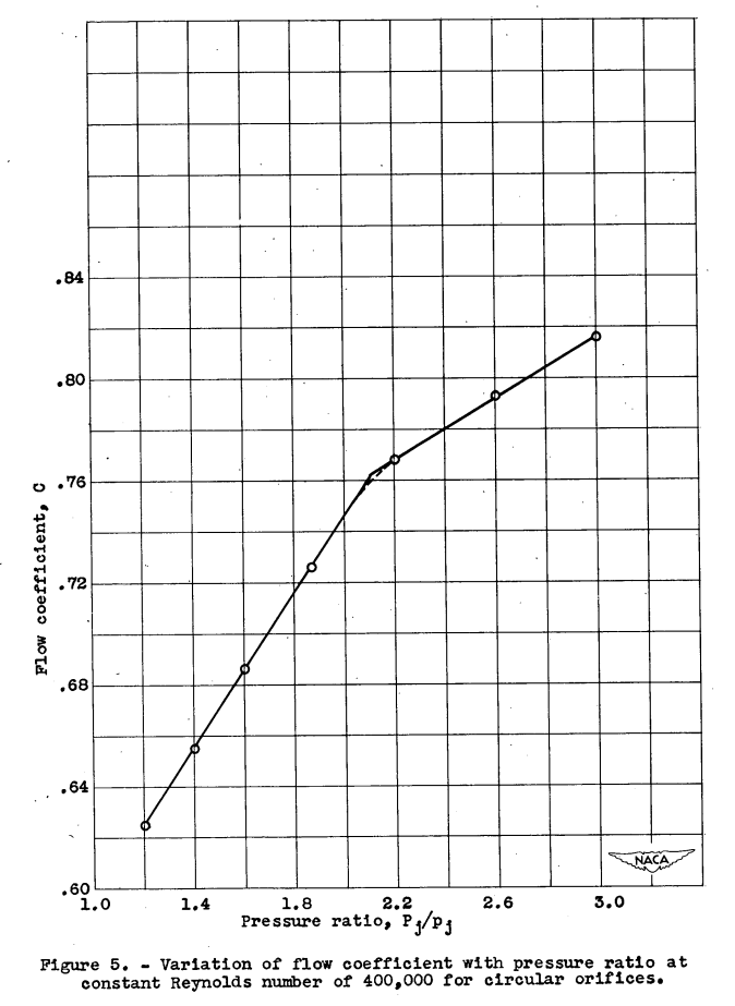
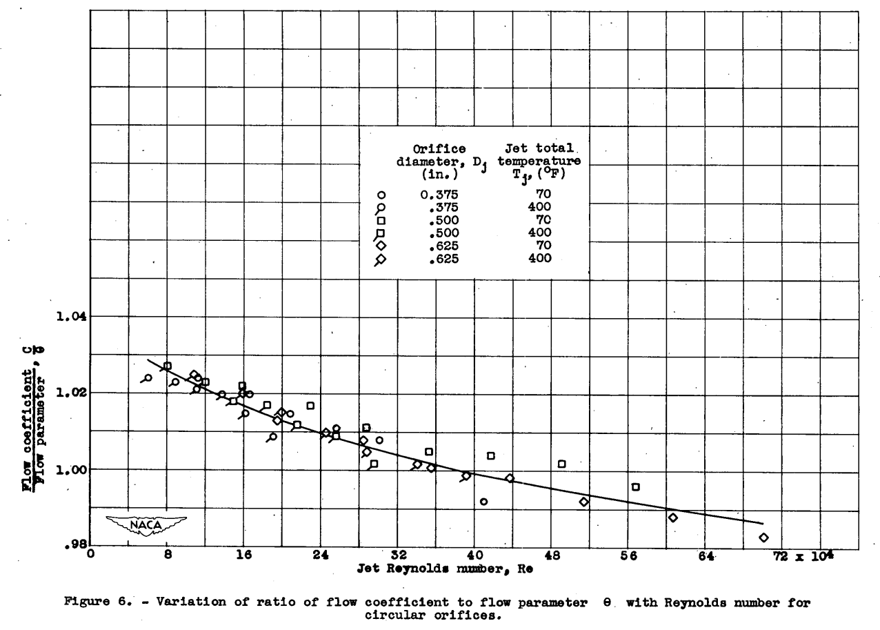
A cross plot of the data in figure 4 showed that at a constant Reynolds number two straight lines almost exactly represented the variation of flow coefficient with pressure ratio (fig. 5). These flow-coefficient relations at constant Reynolds number were utilized as a parameter θ. From a replot of the data in figure 4 as the variation of flow parameter C/θ with Reynolds number, a single curve was obtained (fig. 6). An equation for this curve has been obtained; It should be noted, however, that represents two functions that are valid only in their defined limits.
Effect of tunnel-air velocity on jet flow
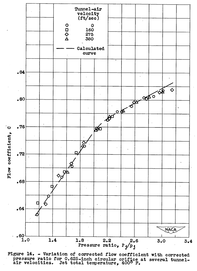
For the initial study of the interaction of the jet and the air stream, the static pressure into which the jet was discharging was assumed equal to the free-stream static pressure of the air stream. The variation of flow coefficient with pressure ratio is shown in figure 13 for a 0.625-inch-diameter circular orifice at a jet total temperature of 4000 F and at tunnel-air velocities of 0, 160, 275, and 380 feet per second. Because the curves were separated by a function that was dependent on the free-stream velocity and because of the relation of static pressure to velocity (Bernoulli's equation), a further investigation of the static pressure into which the jet was discharging was undertaken.
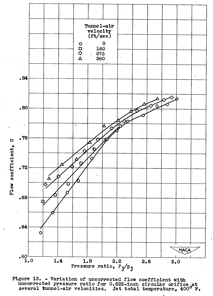
Measurements were made of the static pressure immediately adjacent to the jet at the point of maximum thickness by a tap located in the tunnel 0.030 inch from the orifice. These data indicated a static pressure considerably lower than free stream and somewhat lower than that indicated by a static tap located on the tunnel wall at the same longitudinal position. Analysis of these data showed that the free-stream static pressure was related to the outlet static pressure in accordance with the Bernoulli and mass-flow equations, provided that the free area at the orifice was based on the tunnel width minus the jet width at the point of maximum thickness. When the data of figure 13 were replotted using the corrected values of flow coefficient and pressure ratio based on the corrected outlet pressure, data were obtained (fig. 14) that were in excellent agreement with the calculated curve for a jet discharging into still air. When this correction was applied to all the data for circular, square, and elliptical orifices, excellent agreement was obtained with the results for a jet discharging into still air. Calculation of the flow coefficient for a jet discharging into an air stream is thus possible when the equations for a jet discharging into still air are employed, provided that the correct outlet pressure is used.

Conclusions
SUMMARY OF RESULTS
The following results were obtained In the investigation of the flow coefficients of circular, square, and elliptical orifices discharging into both a still and a moving air stream.
1. Equations were obtained for the flow coefficients for the various shapes in terms of pressure ratio and Jet Reynolds number.
2. Agreement was obtained between the experimental results for three-dimensional flow with circular orifices and the theoretical results for two-dimensional flow.
3. The flow coefficient increased linearly with increasing pressure ratio for pressure ratios up to choking. A transition region was obtained at pressure ratios slightly higher than choking and the flow-coefficient variation again became linear with pressure ratio for the high values of pressure ratio.
4. The flow coefficient Increased more rapidly at the low pressure ratios than at high pressure ratios.
5. The flow coefficient decreased with Increasing jet Reynolds number at constant pressure ratios.
6. For a particular value of pressure ratio and jet total temperature, the ellipses yielded the highest flow coefficients.
7. No effect of stream velocity on flow coefficient was obtained, provided that the proper outlet static pressure was utilized.
Citations
This publication is cited 54 times, per scholar.google.com, with some recent citations.
Notes
-
Callaghan, Edmund E., and Bowden, Dean T.: Investigation of Flow Coefficient of Circular, Square, and Elliptical Orifices at High Pressure Ratios. NACA-TN-1947, 1949. ntrs.nasa.gov ↩