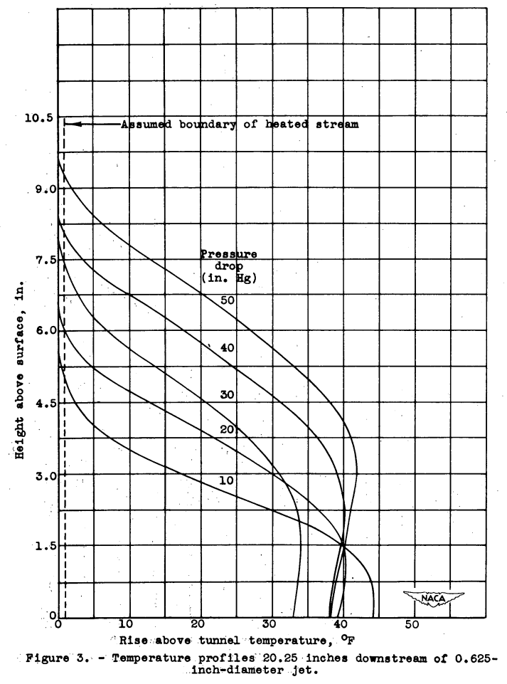
"it was necessary to define the penetration as the point at which the temperature is 1° F above the free-stream total temperature"
"Investigation of the Penetration of an Air Jet Directed Perpendicularly to an Air Stream" 1
An experimental investigation was conducted to determine the penetration of a circular air jet directed perpendicularly to an air strewn as a function of jet density, jet velocity, air-stream density, air-stream velocity, jet diameter, and distance downstream from the jet. The penetration was determined for nearly constant values of air-stream density at two tunnel velocities, four jet diameters, four positions downstream of the jet, and for a large range of jet velocities and densities. An equation for the penetration was obtained in terms of the jet diameter, the distance downstream from the jet, and the ratios of jet and. air-stream velocities and densities.
Discussion
INTRODUCTION The introduction of a gas or vapor into an air stream for the purpose of heating the air stream by mixing or burning often necessitates rapid mixing of the gas or the vapor with the air stream. The high degree of turbulence created by a jet directed perpendicularly to an air stream offers a means of obtaining satisfactory mixing. The jet must rapidly penetrate the air stream in order that this mixing be accomplished in a short distance. One method of obtaining adequate penetration is the utilization of the kinetic energy of a high-velocity jet.
An investigation to determine the penetration of a high-velocity circular air jet directed perpendicularly to an air stream was undertaken in a 2- by 20-inch-duct tunnel at the NACA Cleveland laboratory. The penetration at several positions downstream of the jet was determined at tunnel velocities of 260 and 360 feet per second for four jet (orifice) diameters and a range of orifice pressure drops from 5 to 50 inches of mercury.
APPARATUS AND PROCEDURE
The experimental investigation consisted of two parts:
(1) calibration of the orifices, and
(2) measurements of the depth at penetration of the jets.Calibration of orifices. - Four thin-plate orifices, 1/16 inch thick and 0.250, 0.375, 0.500, and 0.625 inch in diameter, were calibrated in still air and the total-pressure distribution at the orifice plane for each jet was determined for a range of static-pressure drops across the orifice.
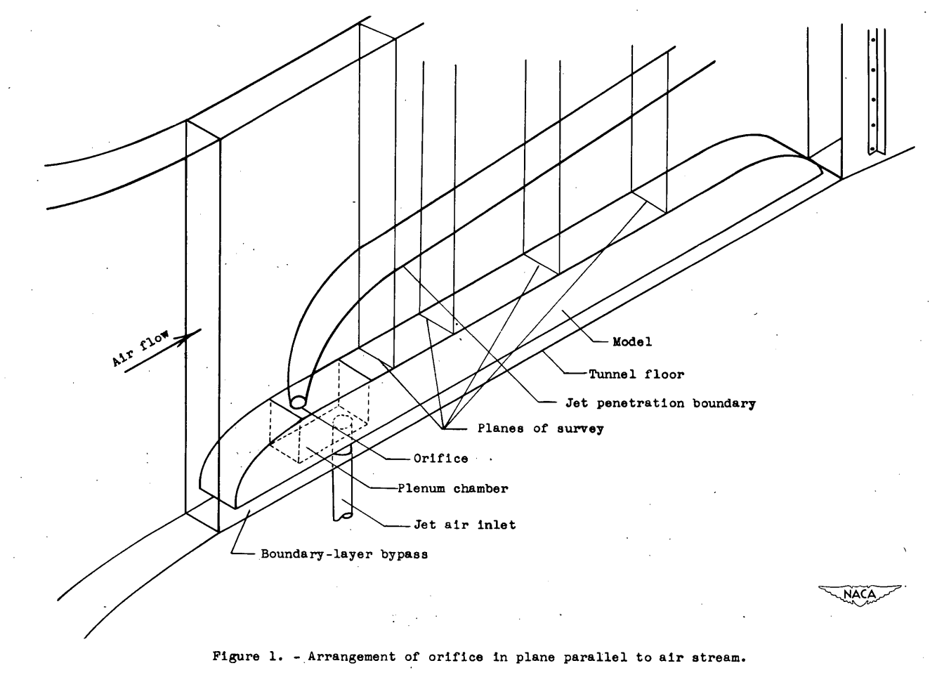
Measurement of depth of penetration. - The penetration of the jet Into the air stream was measured at four positions downstream at the orifice center line. At the rearmost position, 20.25 inches downstream, a permanent rake was used that consisted of 22 total-pressure tubes and 22 thermocouples alternately spaced 1/2 inch apart. An adjustable rake consisting at 24 thermocouples spaced on 1/4-inch centers was used to measure the penetration 4.63, 7.94, and 14.19 inches downstream of the orifice center line. At each position of the adjustable rake, the jet penetrations were investigated for a range of static-pressure drops from 5 to 50 inches of mercury at tunnel velocities of approximately 260 and 360 feet per second for nearly constant values of air-stream density. In order to facilitate the determination of the penetration, heated air for the jet was supplied at approximately 400° F by passing the air through an electric heater. From the heater, the air was passed into a plenum chamber, the upper wall of which contained the jet orifice, as shown in figure 1.
The temperature data were recorded on a flight recorder and the pressure data were photographed from a multiple manometer.
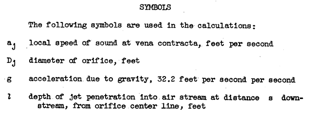
METHODS OF CALCULATION
The total-pressure distribution across the orifices indicated a uniform total pressure for a large part of the diameter, as shown in figure 2.
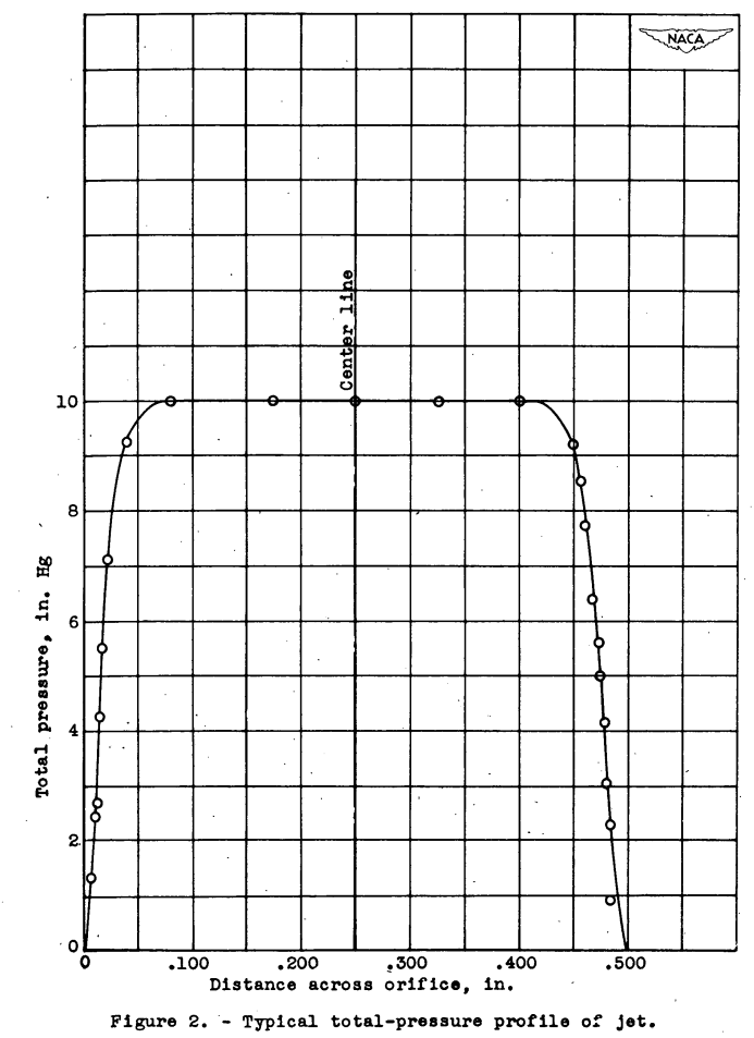
Because of this uniform distribution, the jet velocity Vi was based on the maximum total pressure. The velocity Vj and the density ρj at the vena contracta, or minimum section,were determined with the compressible-flow relations for the subsonic or unchoked condition.
When the static-pressure ratio across the orifice exceeded that necessary for choking, the jet velocity at the vena contracta equalled the local speed of sound in the heated air. The jet velocity at the vena contracta for this case was determined from the following equation:

The jet velocity for the choked condition was determined from the total temperature and the total pressure by using the following equation:

RESULTS AND DISCUSSION
A simple dimensional analysis involving the known variables was made and the following result obtained:

In order to evaluate the penetration from the temperature profiles, it was necessary to define the penetration as the point at which the temperature is 1° F above the free-stream total temperature. This arbitrary assumption was made because of the difficulty encountered in determining the exact point at which the temperature returned to free-stream total temperature owing to the rapid change in curvature of the profiles near this point, as shown in figure 3. The variation in the maximum temperature rise of the various curves is caused by the change in jet-air temperature and the change in jet mass flow.
In order to simplify the analysis of the data, it was necessary to consider the data in terms of a single jet diameter and a single rake position. Thus the mixing distance-diameter ratio s/Dj and the width coefficient w/Dj became constant. In addition, because the jet temperatures were nearly constant, the variation of the viscosity ratio μj/μo was very small and its effect was not considered. In this way, all the parameters except the density ratio ρj/ρ0, the velocity ratio Vj/Vo, and the jet Reynolds number ρj Vj Dj / μj were eliminated. The penetration coefficient l/Dj was plotted as a function of the product of the density and velocity ratios and a single curve was obtained.
Because no consistent trend in these data could be observed, the effect of jet Reynolds number was considered to be small. Similar plots for other values of the jet diameter at the same rake position yielded a family of curves. The family of curves obtained at the 7.94-inch rake station for the four values of jet diameter are shown in figure 4.
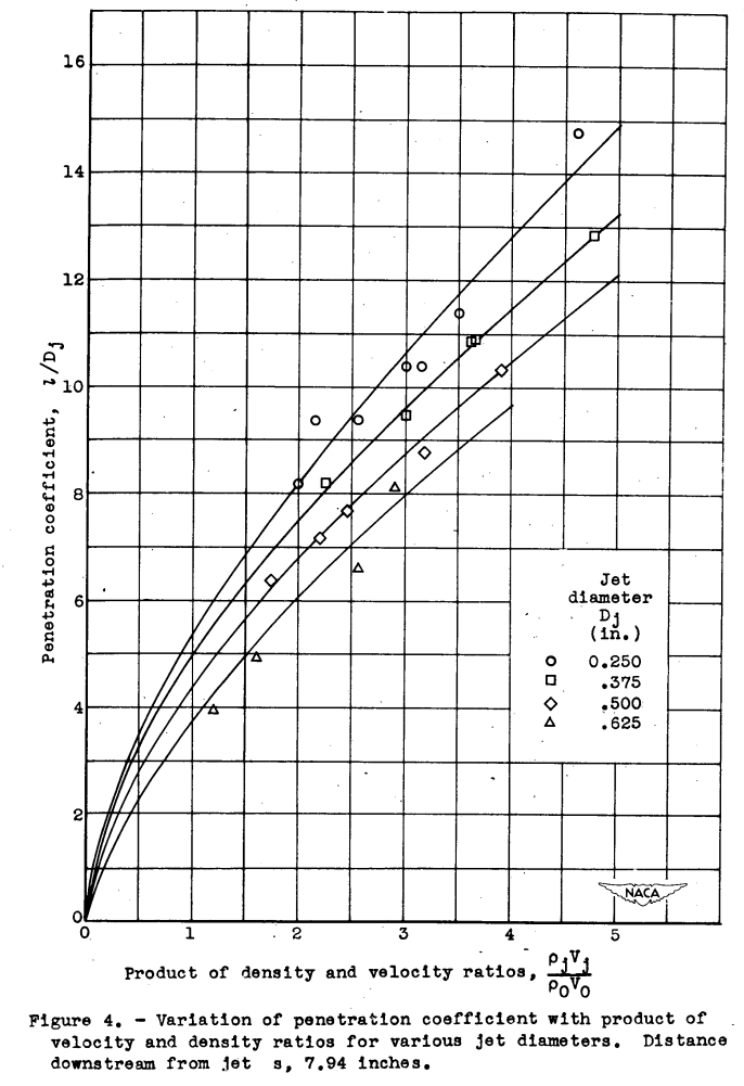
Further analysis of this figure indicated that the member curves were separated. by a factor that was equal to (1/Dj)^0.5. It was therefore possible to plot penetration coefficient against the product of the density ratio, velocity ratio, and the previously determined factor (1/Dj)^0.5 and to obtain a single curve.
A similar procedure was followed for the remaining rake stations and a single curve was obtained for each rake position by using the same parameters and factor. It was not obvious, however, whether the width coefficient or the mixing distance - diameter ratio was the primary variable separating the curves because both the width and the distance downstream were constant. When these plots were combined, the family of curves shown in figure 5 was obtained.
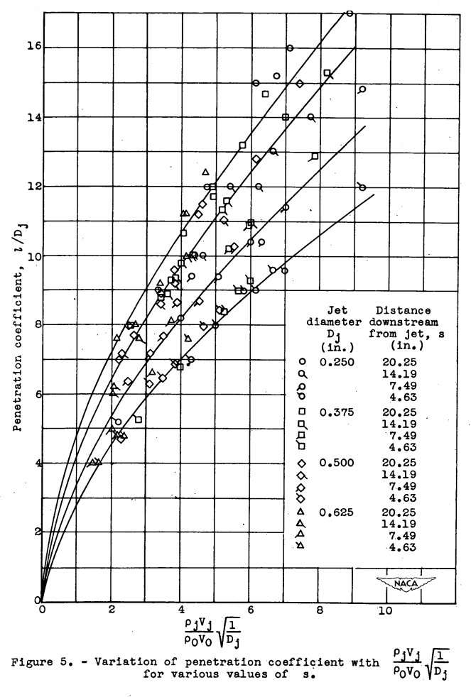
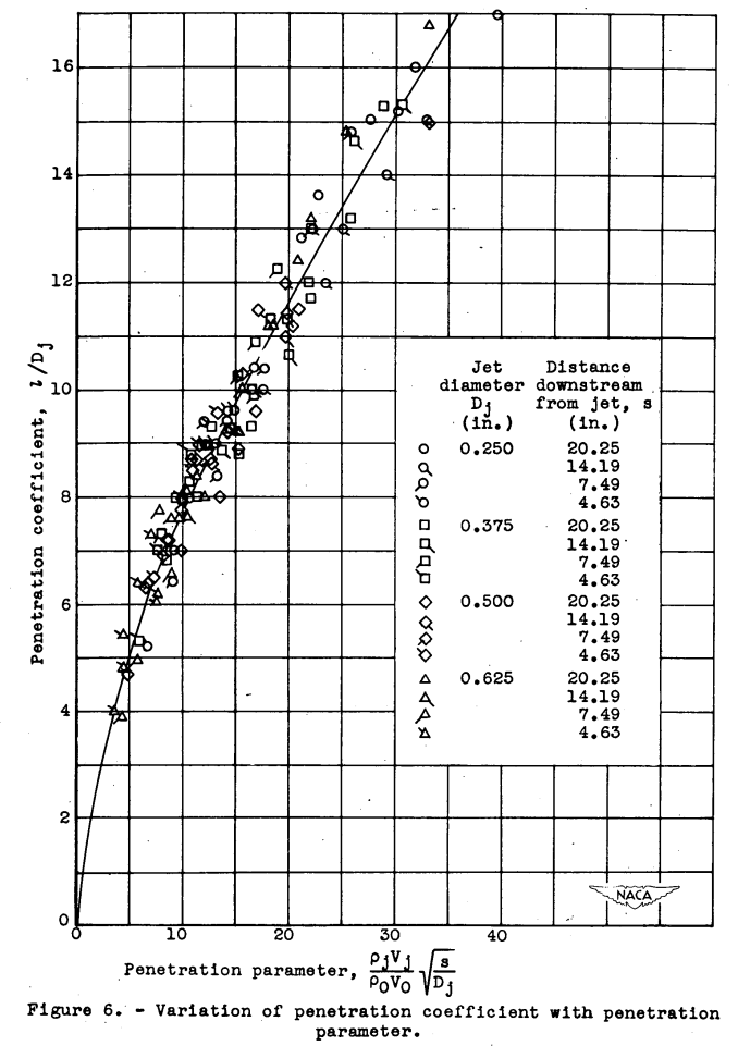
Because the width was invariable, the mixing distance was assumed to be the primary variable separating the curves. A plot of the penetration coefficient against the product of the velocity ratio, density ratio, and the square root of the mixing distance - diameter ratio was constructed and a single curve was obtained (fig. 6). Because no consistent scatter could be observed in the data, the effect of viscosity ratio and jet Reynolds number for-all-the jets is indicated to be small for a range of viscosity ratios from 1.5 to 1.9 and jet Reynolds numbers from 60,000 to 500,000 .

A factor that probably increased depth of penetration in these experiments is the confining effect of the tunnel walls. For a range of width coefficients from 3.2 to 8.0, however, no effect could be found.
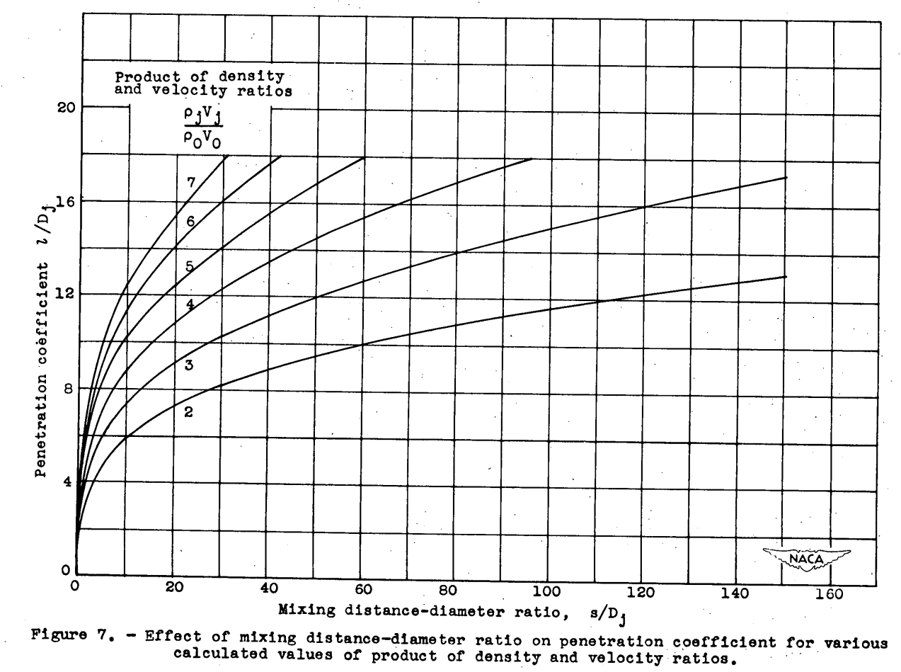
An equation that fitted the experimental curve of Figure 4 has been obtained:

Curves of the mixing distance - diameter ratio as a function of the penetration coefficient for constant' values of the product of the density and velocity ratios as obtained from this equation are shown in figure 7. These curves indicate the actual shape of the penetration boundary.
Conclusions
From an investigation to determine the penetration of an air jet directed perpendicularly to an air stream, the following results were obtained:
1. The following empirical equation was determined for the penetration coefficient-in terms of the density ratio, the velocity ratio, and the mixing distance - diameter ratio:
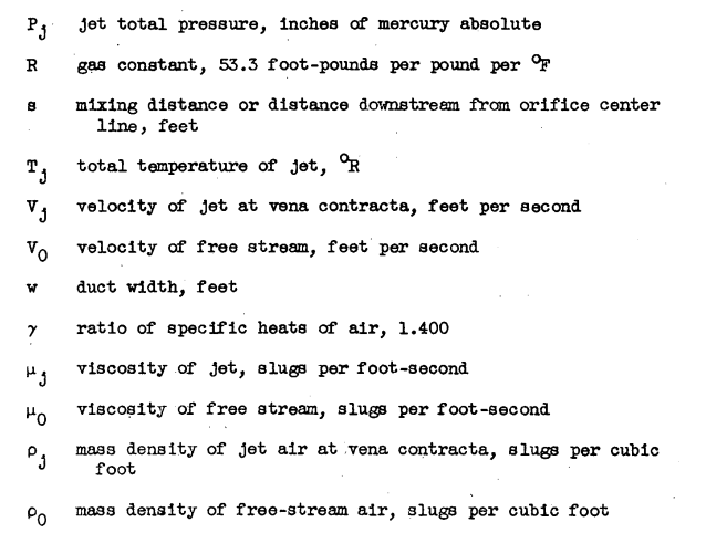
where l is depth of jet penetration into air stream at distance s downstream from orifice center line; Dj, orifice diameter; ρj, mass density of jet air at vena contracta; ρo, mass density of free-stream air; Vj, velocity of jet at vena contracta; and Vo, velocity of free stream.
2. The variation of penetration coefficient with jet Reynolds number, width coefficient, and viscosity ratio was found to be negligible for a range of jet Reynolds numbers from 60,000 to 500,000, a range of width coefficients from 3.2 to 3.0, and a range of viscosity ratios from 1.5 to 1.9.
Citations
This publication is cited 85 times, per scholar.google.com, including several recent publications.
Notes
-
Callaghan, Edmund E., and Ruggeri, Robert S.: Investigation of the Penetration of an Air Jet Directed Perpendicularly to an Air Stream. NACA-TN-1615, 1948. ntrs.nasa.gov ↩