"The engine was satisfactorily accelerated to take-off power after approximately 45 minutes in the icing condition"
"Natural Icing of an Axial-Flow Turbojet Engine in Flight for a Single Icing Condition" 1
Abstract
An investigation has been conducted In natural icing conditions to determine the effect of ice formations on the performance of an axial-flow turbojet engine. One flight was made in an icing condition in which the liquid.-water content varied from 0.077 to 0.490 gram per cubic meter and the average droplet size varied from 5.4 to 12.1 microns. During a period of 60 minutes in icing, at an engine speed of 11,000 rpm, the tail-pipe temperature increased from 8650 to 9650 F and the jet thrust decreased from 1950 to 1700 pounds. Near the end of the icing period, the engine was satisfactorily accelerated to take-off power.
Discussion
As this publication is brief (12 pages, with seven of those photos), it is reproduced nearly in its entirety herein.
The jet engine inlet in this case did not have ice protection.
INTRODUCTION
An investigation has been conducted in natural icing conditions at the NACA Cleveland laboratory to determine the effect of ice formation on the performance of an axial-flow turbojet engine. Data presented herein were obtained during one flight at an engine speed of 11,000 rpm, the normal cruising speed of the engine. Data obtained on a previous flight at an engine speed of 9000 rpm are presented in reference 1. During the icing condition, the engine was accelerated to 12,000 rpm, or take-off power. Attempts will be made to obtain additional performance data in other icing conditions.APPARATUS
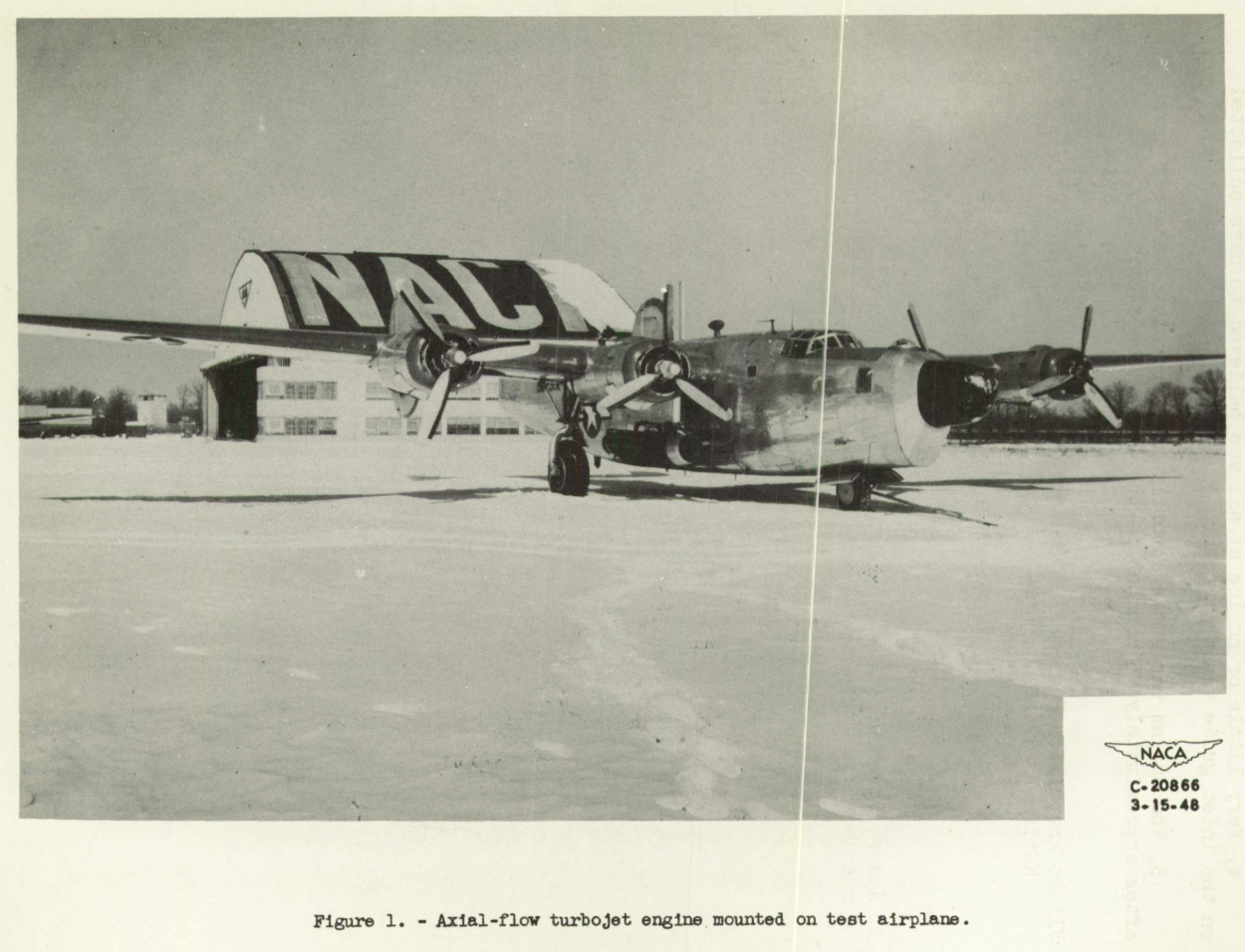
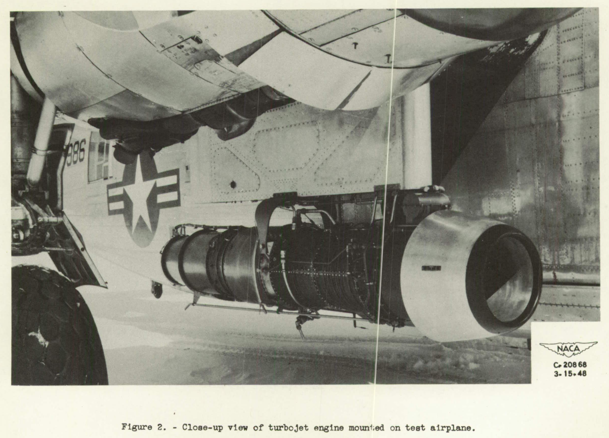
A 24C-2 turbojet engine was mounted on a four-engine bomber, which was provided with anti-icing equipment for the wings, the tail surfaces, and the propellers. General and close-up views of the installation are shown in figures 1 and 2, respectively. The turbojet engine used. for this investigation has a 10-stage axial-flow compressor, a two-stage turbine, and an annular combustion chamber. The characteristics of the engine are:
Maximum engine speed, rpm ..........12,000
Cruising engine speed, rpm .........11,000
Static-thrust rating, pounds .........2800
Maximum tail-pipe temperature, °F ....1220
Instrumentation was provided at the compressor outlet for calculation of compressor efficiency and at the tail-pipe outlet for calculations of air flow and thrust. A deflecting-vane-type flow-meter was used to measure the fuel flow to the engine.
RESULTS AND DISCUSSION
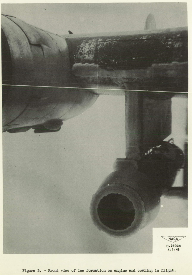
The ice formation obtained on the jet-engine cowling inlet is shown in figure 3.
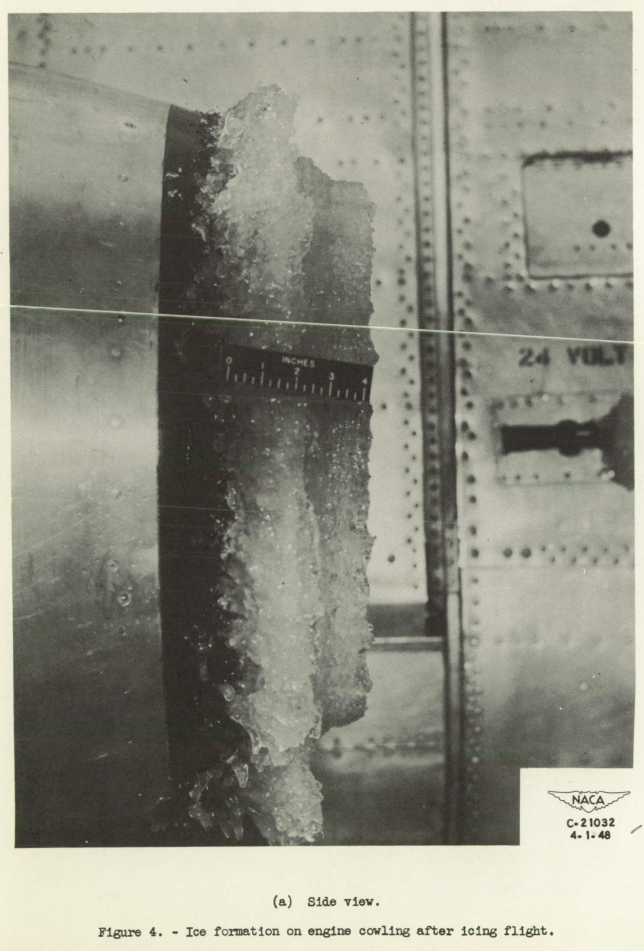
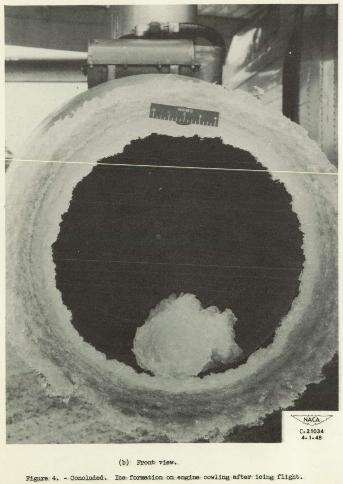
The degree of ice accumulation on the engine inlet is indicated by figures 4(a) and 4(b), which are side and front views, respectively, of the engine inlet photographed after landing. Very little ice, if any, collected on the engine-inlet guide vanes. The ice shown at the bottom of the inlet guide vanes is believed to consist of pieces broken from the ice formation on the starter housing or the support struts.

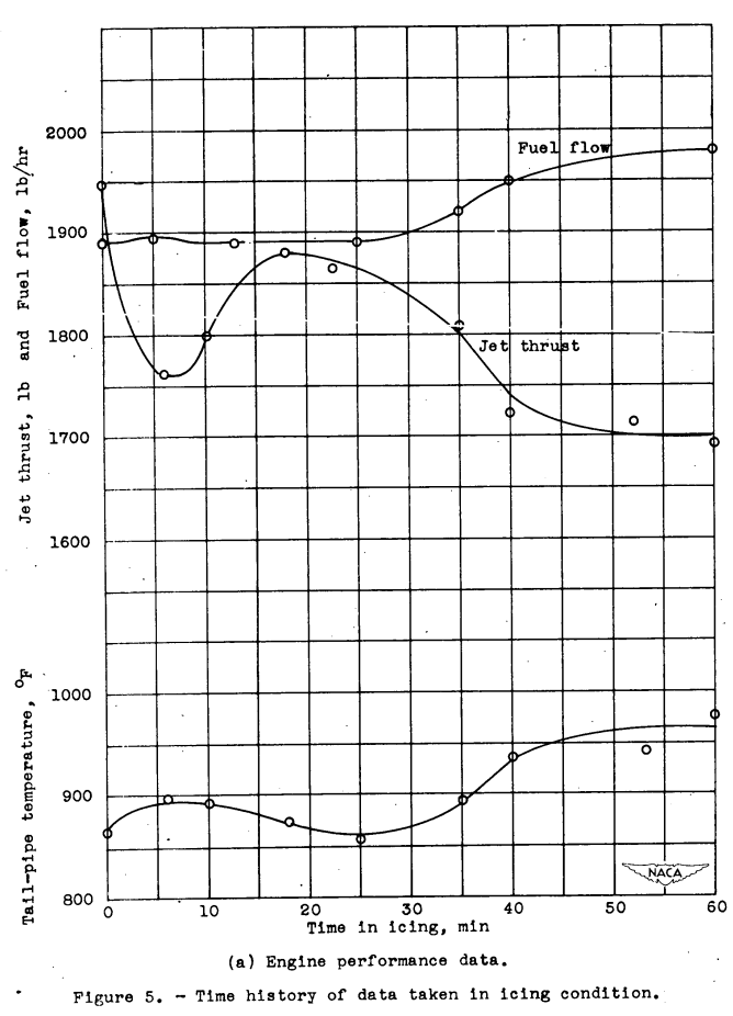
A time history of the data taken in the icing condition is shown in figure 5. Engine jet thrust, fuel flow, and tail-pipe temperature are shown in figure 5(a); average droplet size, free-air temperature, and liquid-water content are shown in figure 5(b). Engine and icing data were taken upon entering the icing cloud, and periodically during the encounter with the icing condition, which lasted for approximately 1 hour. The engine speed was maintained at 11,000 rpm. A sudden drop in engine thrust as the airplane entered the icing cloud is believed to be a result of ice collection on the cowl lip, which disrupted the air flow and destroyed the pressure recovery at the compressor inlet.
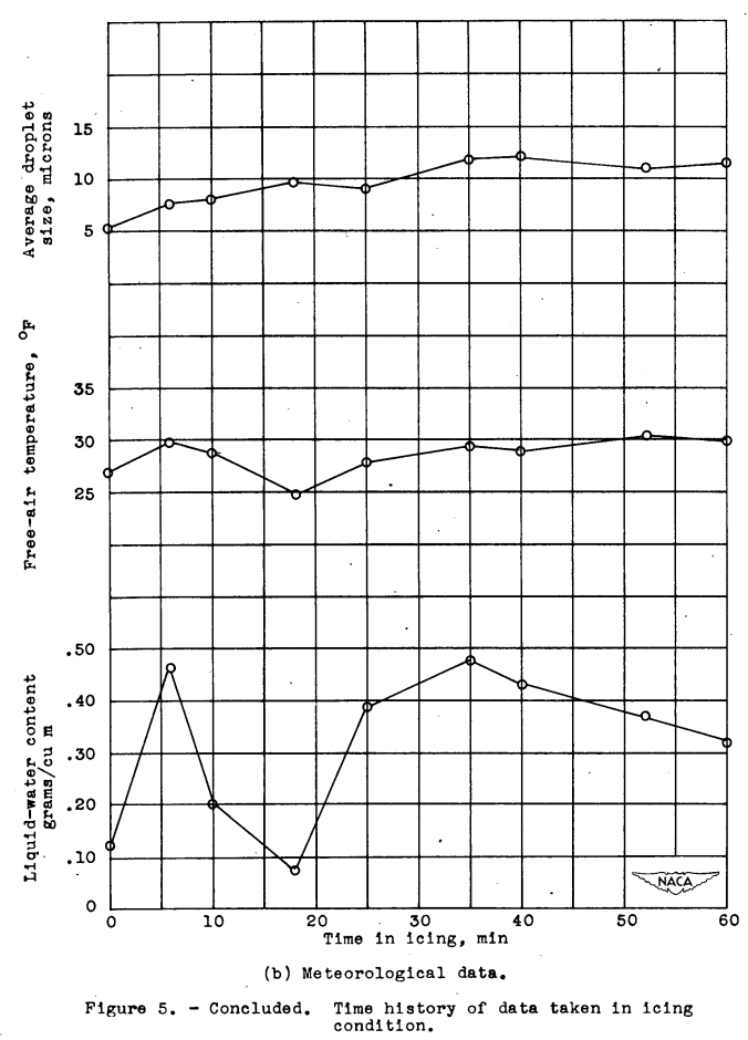
After 18 minutes in the icing condition, the engine returned to nearly normal operation. Because of the very low liquid-water content at that time (0.077 gram per cubic meter) and high free-air temperature (25° F), the ice accumulation on the engine inlet melted and ran back along the cowling (fig. 5(b)).
After 35 minutes, the liquid-water content rapidly rose to 0.49 gram per cubic meter (fig. 5(b)). The fuel flow then increased to maintain the engine speed, which resulted in a corresponding increase in tail-pipe temperature. At this point the thrust rapidly decreased.
After 35 minutes, the liquid-water content gradually decreased from 0.49 to 0.32 gram per cubic meter at the end of the run (fig. 5(b)). The additional ice accumulation on the engine resulted in a gradual increase in fuel flow and tail-pipe temperature and a gradual decrease in jet thrust.
At the end of 60 minutes, the thrust, the tail-pipe temperature, and the fuel flow had stabilized (fig. 5(a)). During the icing encounter, the thrust decreased from 1950 to 1700 pounds, the tail- pipe temperature Increased, from 865° to 965° F, and the fuel flow increased from 1890 to 1980 pounds per hour. During the time in the Icing condition, the free-air temperature varied from 25° to 31° F, the average droplet size varied from 5.4 to 12.1 microns, and the liquid-water content varied from 0.077 to 0.490 gram per cubic meter (fig. 5(b)).
The engine was accelerated to take-off power of 12,000 rpm and held at this speed for 2 minutes after approximately 45 minutes in the icing condition. At the end of 2 minutes, the tail-pipe temperature had stabilized. The ice shown In the photographs resulted in a thrust decreased at 12,000 rpm from 2455 to 2050 pounds and a tail-pipe temperature increase from 1063° to 1139° F.
No general conclusions may be drawn from these data, but no serious reduction in engine performance would be experienced in an icing condition similar to the one discussed.
Conclusions
SUMMARY OF RESULTS
The following results were obtained with an axial-flow turbojet engine in one icing encounter in natural icing conditions with an average droplet size of approximately 10 microns, free-air temperature of approximately 30° F, and liquid-water content varying from 0.077 to 0.490 gram per cubic meter:
1. The tail-pipe temperature increased from 865° to 965° F during an icing period of 60 minutes.
2. The engine jet thrust decreased from 1950 to 1700 pounds during the same period.
3. The fuel flow increased from 1880 to 1980 pounds per hour during the icing run.
4. Very little or no ice at all was believed to have collected on the inlet guide varies or rotor.
5. The engine was satisfactorily accelerated to take-off power after approximately 45 minutes in the icing condition.
Citations
This publication is cited by one publication, per scholar.google.com:
- von Glahn, Uwe H., Callaghan, Edmund E., and Gray, Vernon H.: NACA Investigations of Icing-Protection Systems for Turbojet-Engine Installations. NACA-RM-E51B12, 1951. ntrs.nasa.gov
Related
This is part of the Engine Inlet Icing Thread.
Notes
-
Acker, Loren W.: Natural Icing of an Axial-Flow Turbojet Engine in Flight for a Single Icing Condition. NACA-RM-E8FO1a ntrs.nasa.gov, 1948. ↩