Articles with tag: "LEWICE"

(Note: figures do not appear in the summaries below)
  1. Using Appendix C for Ice Shape Analysis

    Published: Mon 29 April 2024
    Updated: Wed 16 October 2024

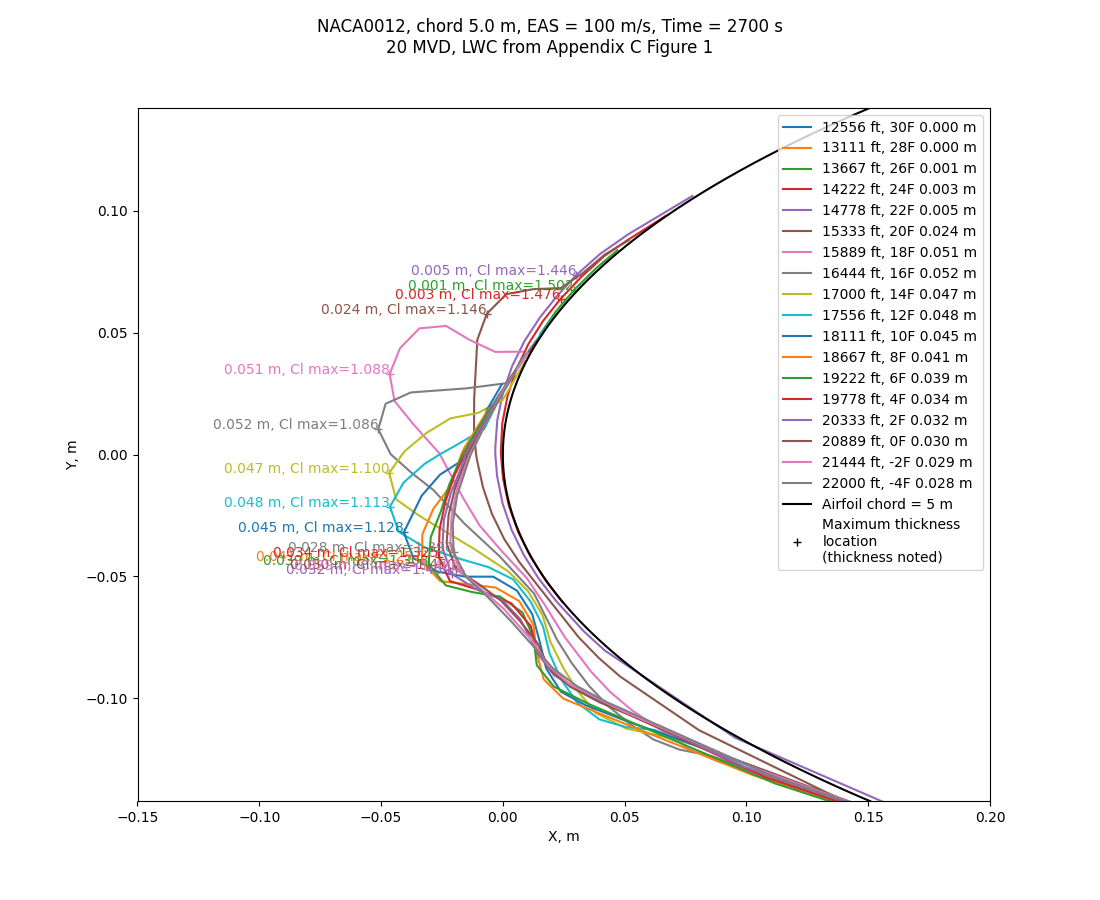
    LEWICE sweep data 20 MVD 100 chord 5.000 m EAS 45 minute ac2073a_ice shapes_with_cls
    Public domain image by Donald Cook.

    Summary

    Search within the Appendix C Continuous Maximum Icing definition for the thickest ice shape.

    Prerequisites

    You need to have completed Run a 2D simulation.

    Introduction

    "Aircraft Ice Protection" AC 20-73A faa.gov offers guidance on analysis for icing conditions. We will not cover the certification aspects in detail.

    Much of the detail is on ice protection systems.

    This advisory circular (AC) tells type certificate and supplemental type certificate applicants how to comply with the ice protection requirements of Title 14 of the Code of Federal Regulations (14 CFR) parts 23, 25, 27, 29, 33, and 35.

    However, it is also useful for analysing ice shapes on unprotected surfaces.

    It is noted that:

    Determination of critical ice shape configurations is not straightforward and may require engineering judgment.

    SAE AIR5903, "Droplet Impingement and Ice Accretion Computer Codes" sae.org notes:

    A balancing of accurate and …

    read more
  2. Introduction to Variations

    Published: Mon 08 April 2024
    Updated: Tue 01 October 2024

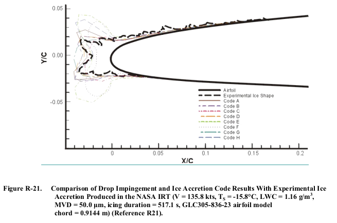
    Figure R-21. Comparison of Drop Impingement and Ice Accretion Code Results With Experimental Ice
Accretion Produced in the NASA IRT (V = 135.8 kts, T S = -15.8°C, LWC = 1.16 g/m 3 ,
MVD = 50.0 ȝm, icing duration = 517.1 s, GLC305-836-23 airfoil model
chord = 0.9144 m) (Reference R21).
    From AC 20-73A faa.gov.

    Summary

    • Different methods (test, analysis methods) can yield different ice shapes for the same conditions
    • Measurements of ice shape parameters characterize the differences
    • What is "too large" of a difference depends on unique factors for a particular case
    • Engineering judgment is required to navigate the differences

    Discussion

    A method to characterize ice shapes

    "Aircraft Ice Protection" AC 20-73A faa.gov lists ice shape parameters that can be used to compare ice shapes:

    Applicants may use the lists of ice shape and water catch evaluation parameters in tables R-1 and R-2, ranked against their adverse airplane effects, to compare simulated and natural ice shapes. These lists are from SAE ARP5903 (Reference R20).

    Table R-1. Ranking of Ice Shape Evaluation Parameters

    Rank Parameter Units Conservatism criteria
    1 Upper (suction surface) horn height Equal or greater horn peak thickness (height)
    2 Upper Horn Angle degree Criticality of location …
    read more
  3. Computer Freezing Rate Analysis Tools Examples

    Published: Mon 08 April 2024
    Updated: Wed 16 October 2024

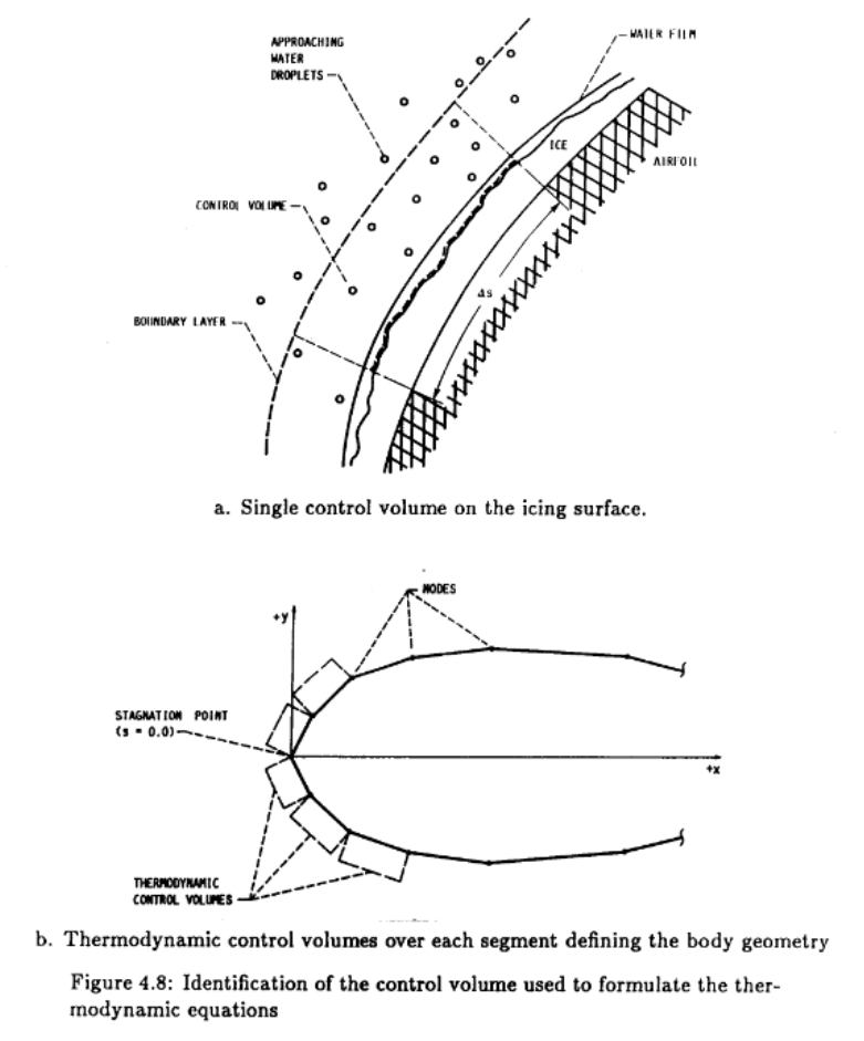
    Figure 4.8: Identification of the control volume used to formulate the thermodynamic equation  
a. Single control volume on the icing surface.  
b. Thermodynamic control volumes over each segment defining the body geometry
    from Users Manual for the NASA Lewis Ice Accretion Prediction Code (LEWICE) (1990 version) ntrs.nasa.gov

    Prerequisites

    You need to complete the Aircraft Icing Handbook Water Catch Examples.

    You need to select a computerized tool to work with. See Analysis Toolset for obtaining LEWICE, and some other options.

    If you have chosen to use LEWICE, but you have not run it before, see the LEWICE Quick Start.

    Introduction

    We will compare energy balance terms and freezing rates calculated with the Standard Computational Model and LEWICE (or the tool that you have selected).

    The values found by differing methods are generally similar, but rarely identical.

    Aircraft Icing Handbook Example 2-4

    The mass of ice accretion on the NACA 0012 section will be calculated. Using the same flight conditions as Example 2-1. and the droplet size distribution and value from Example 2-3:

    Airfoil                         c = 3.1 foot chord NACA 0012  
    Flight …
    read more
  4. Computer Impingement Analysis Tools Examples

    Published: Mon 08 April 2024
    Updated: Tue 01 October 2024

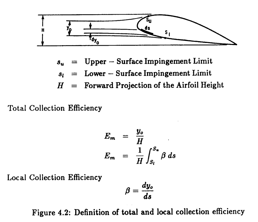
    LEWICE 1990 Figure 4.2. Definition of total and local collection efficiency.
    from Users Manual for the NASA Lewis Ice Accretion Prediction Code (LEWICE) (1990 version) ntrs.nasa.gov

    Prerequisites

    You need to complete the Aircraft Icing Handbook Water Catch Examples.

    You need to select a computerized tool to work with. See Analysis Toolset for obtaining LEWICE, and some other options.

    Aircraft Icing Handbook Example 2-2

    Example 2-2
    This example illustrates the estimation of the impingement parameters E, β, h, Su and SL using graphical data (reference 2-12). The graphical data is all presented with Ko as the independent variable. Much data is available in this form.

    The conditions of Example 2-1 for a NACA 0012 airfoil are assumed: thus Ko = 0.05. It also is assumed for simplicity that the angle of attack, α, is 0 degrees. From figure 2-11, E, the total impingement efficiency, is estimated to be 0.23 for these conditions. So about 23 percent of the water …

    read more
  5. LEWICE Quick Start

    Published: Mon 08 April 2024
    Updated: Wed 16 October 2024

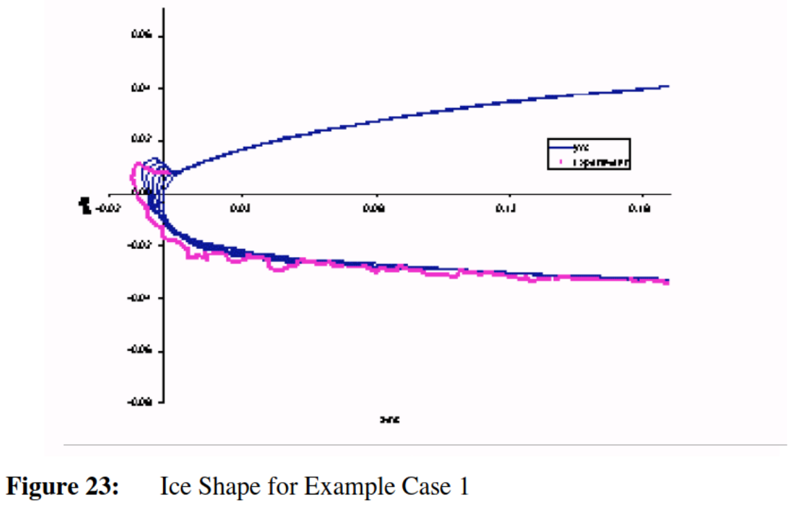
    LEWICE Ice Shape for Example Case 1. A 2D profile of an airfoil with a calculated ice shape 
and an ice shape measured in an icing  wind tunnel test.
    from User's Manual for LEWICE Version 3.2 ntrs.nasa.gov

    Summary

    The "least that you need to know" to start using LEWICE, the NASA-provided icing simulation tool.

    Prerequisites

    See Analysis Toolset for how to obtain LEWICE.

    Introduction

    Decades ago there was training available for using LEWICE. I do not know of recent training. You are largely on your own, with the manual and supporting material.

    This certainly does not contain complete information, but it will help you get started in the basics of running LEWICE.

    Discussion

    The LEWICE manual provides these instructions:

    3.1.
    LEWICE Quick Start Guide
    This section is intended for users unfamiliar with LEWICE and/or DOS Shell commands. The commands below (indented bold lines) should be typed at the C:\ prompt in a DOS Shell window on a Windows machine. Alternatively, the user can use the Windows interface for any of the commands shown. Windows …

    read more
  6. Analysis Toolset

    Published: Mon 08 April 2024
    Updated: Tue 01 October 2024

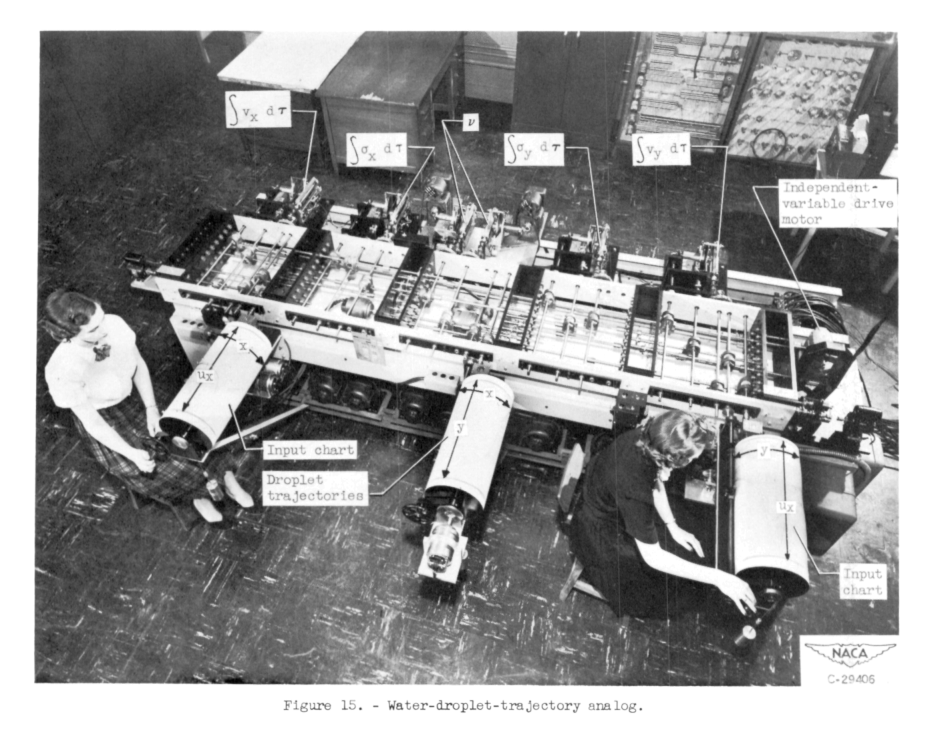
    Figure 15 of NACA-TN-2904. Water-drop-trajectory analog.
Two investigators operate a large mechanical computer. 
One is seated turning a crank attached to a large cylinder labelled "Input Chart". 
The second operator turns another input chart crank. 
Another cylinder is labelled "Droplet Trajectories". 
There are many shafts and gears visible in the machine. 
Some machine parts are labelled with the differential equations of motion being solved.
    Figure 15 of NACA-TN-2904 ntrs.nasa.gov.

    Summary

    You will have to choose a toolset to perform the example analyses.

    Example calculations are provided in the Python programming language, and using the NASA-provided LEWICE code.

    Introduction

    You are highly encouraged to perform the analysis described in the examples (and not just read the examples). Some examples can be accomplished with hand calculations, while other require computational capabilities.

    You need to select your toolset.

    Consider your current and future uses

    A toolset is an investment of your time and resources. By performing the calculation of the examples used here, you will build your personal and software capabilities and skills.

    Your toolset at a particular time may not be entirely your choice. Your company, institution, or customer may have policies on which kinds of software are required, encouraged, discouraged, or prohibited. Some codes have by-country use restrictions. You may have signed an …

    read more